We use cookies to make your experience better. To comply with the new e-Privacy directive, we need to ask for your consent to set the cookies. Learn more.
Formlabs Maintenance
Troubleshooting
Cleaning after a failed print (Form 3)
This article applies to Form 3
Occasionally, a print may fail to complete. Failed prints often leave small, partially cured pieces of resin floating in the tank or hard cured resin stuck to the flexible film at the bottom of the tank. Before a new print is started, the resin tank must be completely cleaned and cleared of debris. For best results, inspect and clean the tank after every print.
Warning:
Resin may cause skin irritation or an allergic skin reaction. Wear gloves when handling liquid resin or resin-coated surfaces. Wash skin with plenty of soap and water. Do not wash skin with products containing alcohol, like hand sanitizer, or any other solvents
Removing cured resin manually
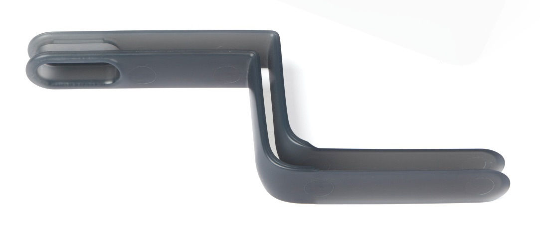
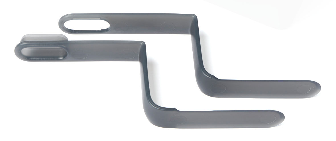
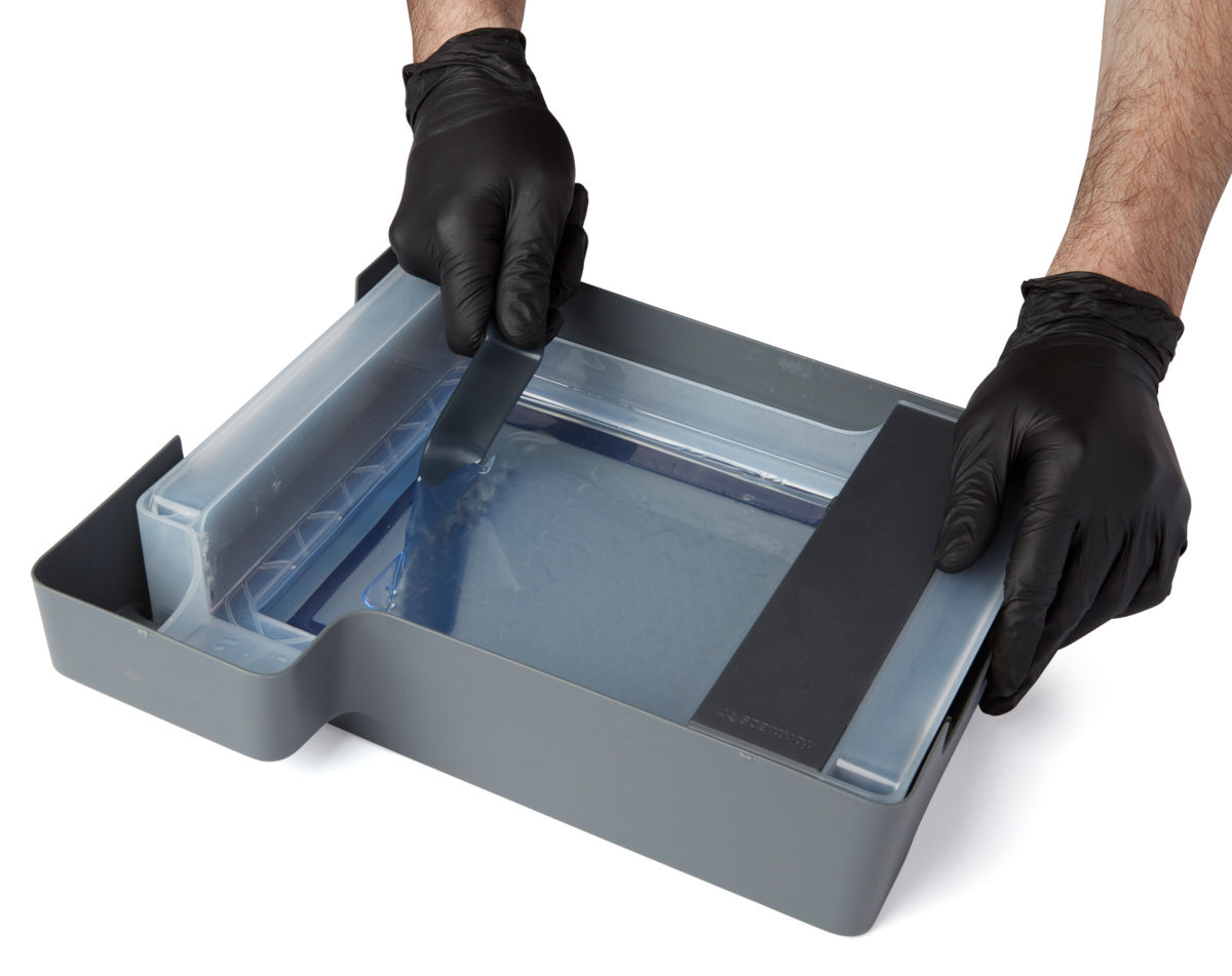
The Form 3 comes with a tank tool, which is a custom two-part scraper and tweezers. The tank tool is made of plastic and has rounded edges to protect the film at the bottom of the tank. Remove individual pieces of cured resin from the tank with the tank tool.
Notice:
Do not use the part removal tool, scraper, flush cutters, or any other metal tool to inspect the Form 3 resin tank or remove cured resin from the tank. Such tools may damage the tank film, leading to failed prints and/or a resin spill.
- Remove the build platform and resin cartridge first to avoid dripping uncured resin into the printer cavity.
- Remove the resin tank and place it in its case on a clean, flat surface. This allows for better visibility and more space to work than leaving the tank in the printer.
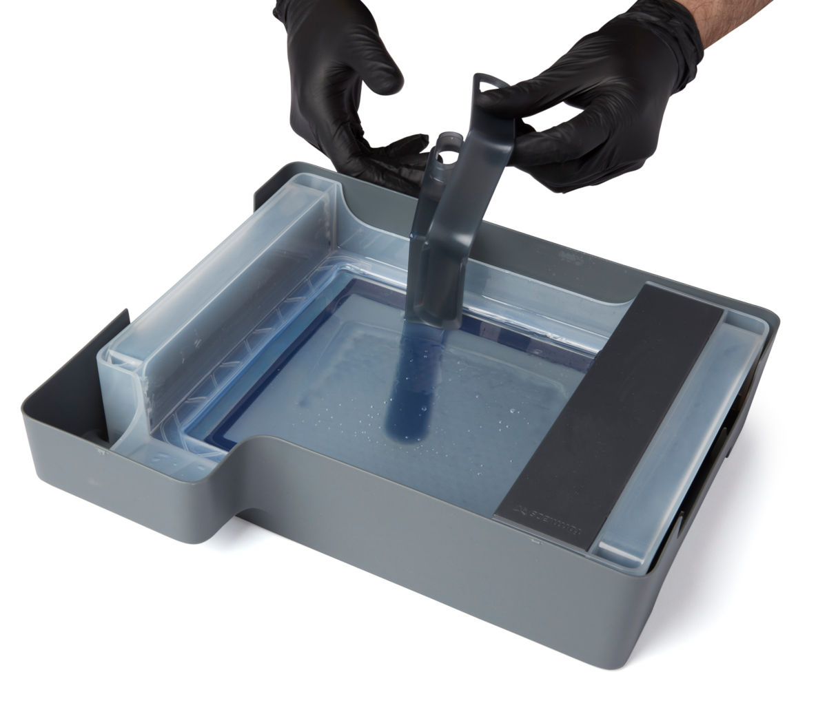
- Separate the two halves of the tank tool.
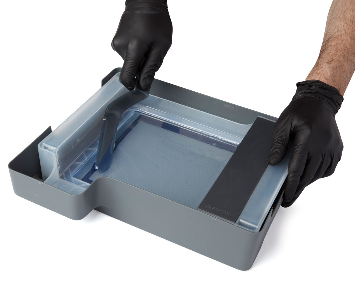
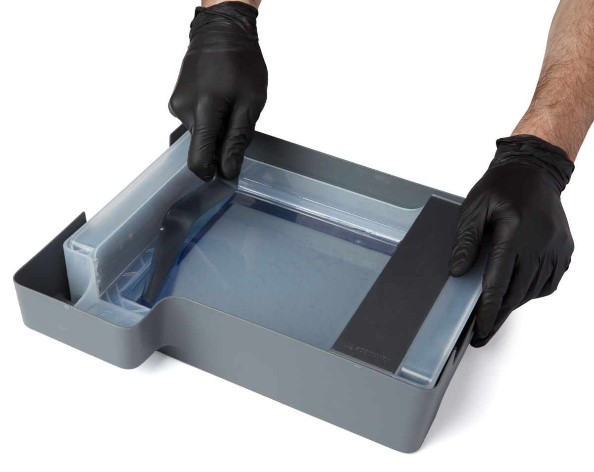
- Use the lower piece of the tank tool to scrape cured resin off of the film.
- Scrape laterally using the long side of the tool to get its edge under the cured resin.
- Continue scraping or twist the tool to lift the resin off of the film.
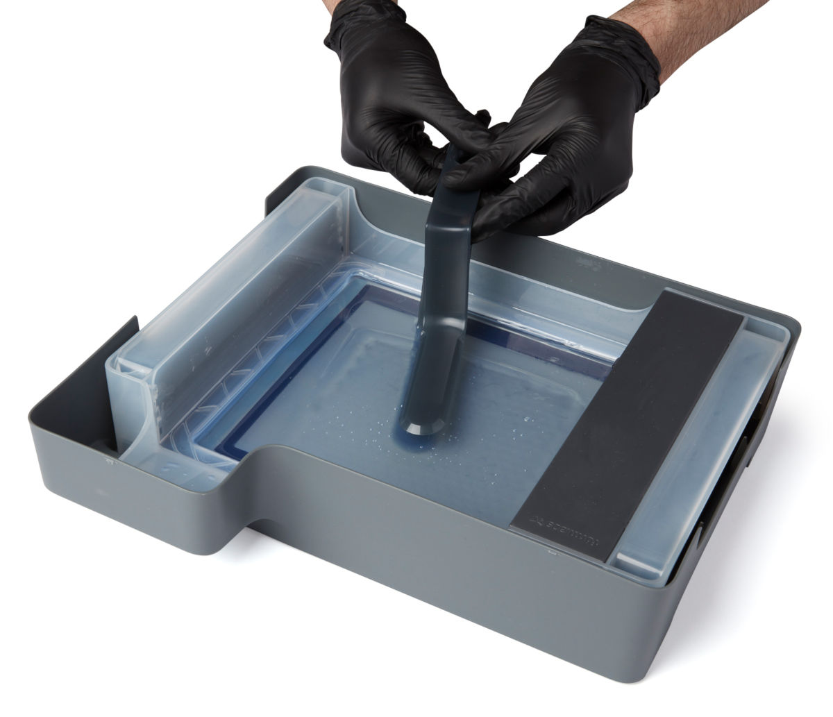
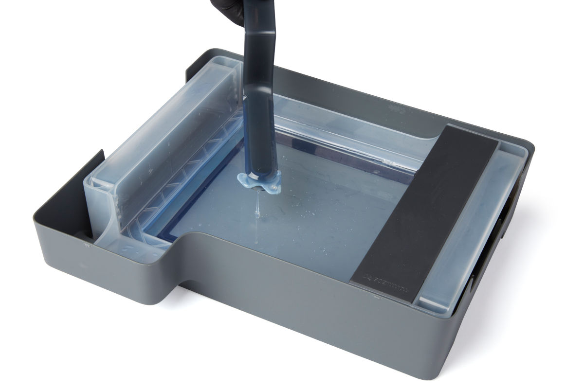
- If the cured resin is difficult to remove with one half of the tank tool, snap the two halves of the tank tool back together and use it as a pair of tweezers to grab floating pieces of cured resin.
- Scrape the film using the edge of the lower half of the tool, then press the top half down onto the cured resin to lift it out of the tank.
Cleaning the tank tool
Clean the tank tool after each use to remove excess liquid resin and prevent contamination.
To clean the tank tool by hand:
- Apply clean IPA to a clean paper towel.
- Wipe the surface of the tank tool to remove resin.
- Allow the tank tool to air dry.
To clean the tank tool using the Form Wash:
- Rest the tank tool in the Form Wash basket.
- Set Form Wash to clean for 5 minutes. Increase the wash time for heavily-used solvent.
- Allow the tank tool to air dry after washing.
Filtering the resin (optional)
After removing the primary print failure, inspect the resin and tank for other small fragments. While the mixer will help keep the print area clear during printing, clean resin and optical transparency in the bottom of the resin tank are always the best way to ensure quality prints.
Notice:
If you see or feel any resin cured in your tank, it's essential to remove debris by cleaning the tank or the next print will fail. Use a paint filter with a "Fine" or 190 micron mesh size to thoroughly strain liquid resin.
Reseating the mixer
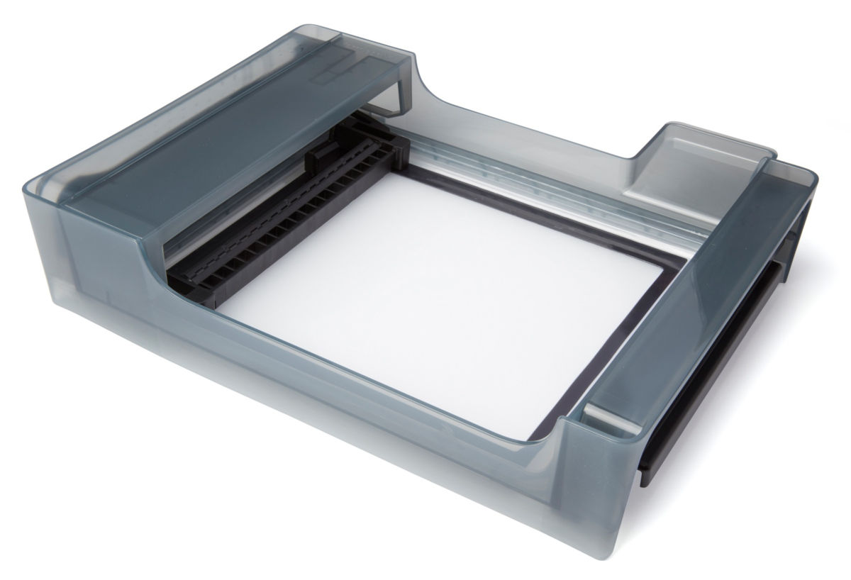
At the start of each print, the LPU housing pulls the tank mixer back and forth across the tank film several times. This motion mixes the resin in the tank while also checking for cured resin on the film and on the build platform. If the mixer encounters cured resin blocking its path, its magnets will decouple from the magnets in the LPU housing and the printer will pause the print. This is the designed behavior of the mixer and is intended to protect the tank film and prevent further print failures.
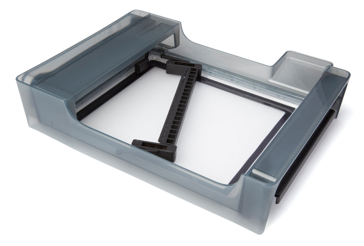
- Open the printer cover.
- Push the mixer back into its home position on the left of the tank.
- Orient the mixer with the arms facing left.
- Slide the mixer left until the arms click into place.
- Inspect the film using the tank tool.
Published date:24-Jun-2019.
Shipping your Form 3
This article applies to Form 3
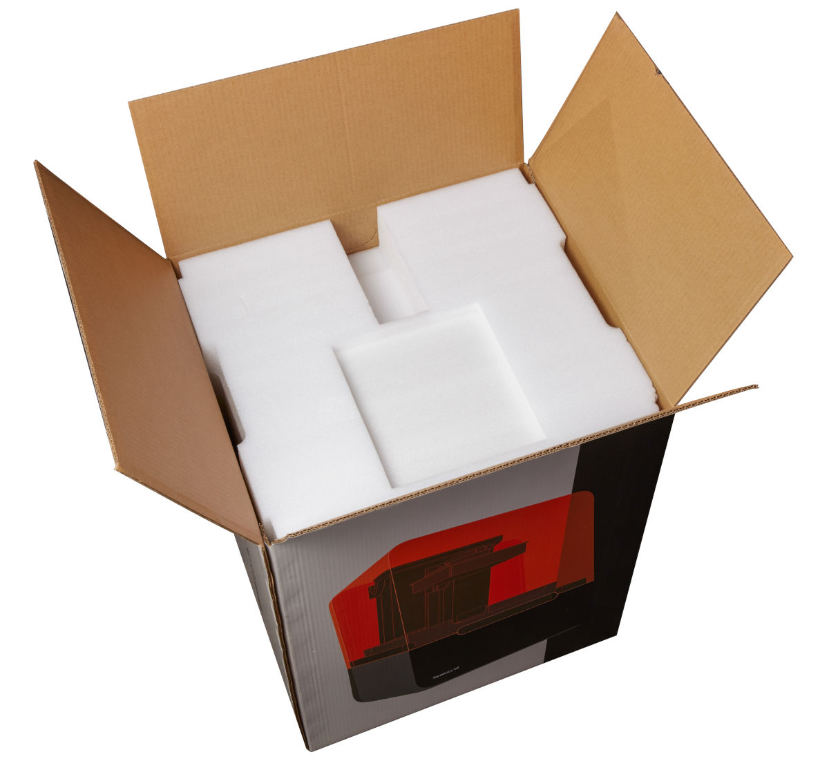
Follow these instructions to package the Form 3 for protection during shipping or transit. The printer’s original packaging is required for warranty service.
Packaging materials
Form 3 packaging materials are designed to be kept and reused for transporting your printer. The printer’s complete packaging kit consists of:
- 1 outer box, cardboard
- 1 lift tray, cardboard
- 1 bottom insert, foam
- 1 upper insert, foam
- 1 shipping latch, metal
- 2 shipping latch screws, metal
Preparing to ship
- Remove the build platform, resin tank, and cartridge before moving or packaging the Form 3, and disconnect the unit from power.
- Wipe any liquid resin off the build platform and store the platform away from sunlight. You may choose to store the build platform in plastic wrap and/or in its original box.
- Store the resin tank in its case with the cover in place.
- Store the cartridge with the vent cap closed and the valve cover installed.
Notice:
If you are shipping a printer to Formlabs for service, do not ship the build platform, resin tank, power and USB cables, and other accessories These items will not be returned after service.
Inspecting and reassembling packaging
- If the printer’s outer cardboard carton has been flattened, start by re-assembling the box and securely taping its bottom opening.
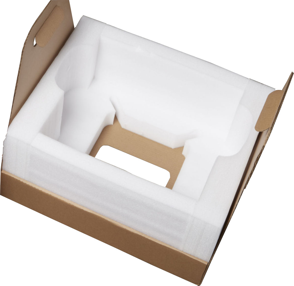
- Insert the bottom foam insert into the cardboard lift tray. The bottom foam insert has a large square hole through its center.
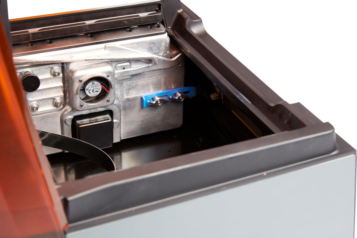
Installing the shipping latch
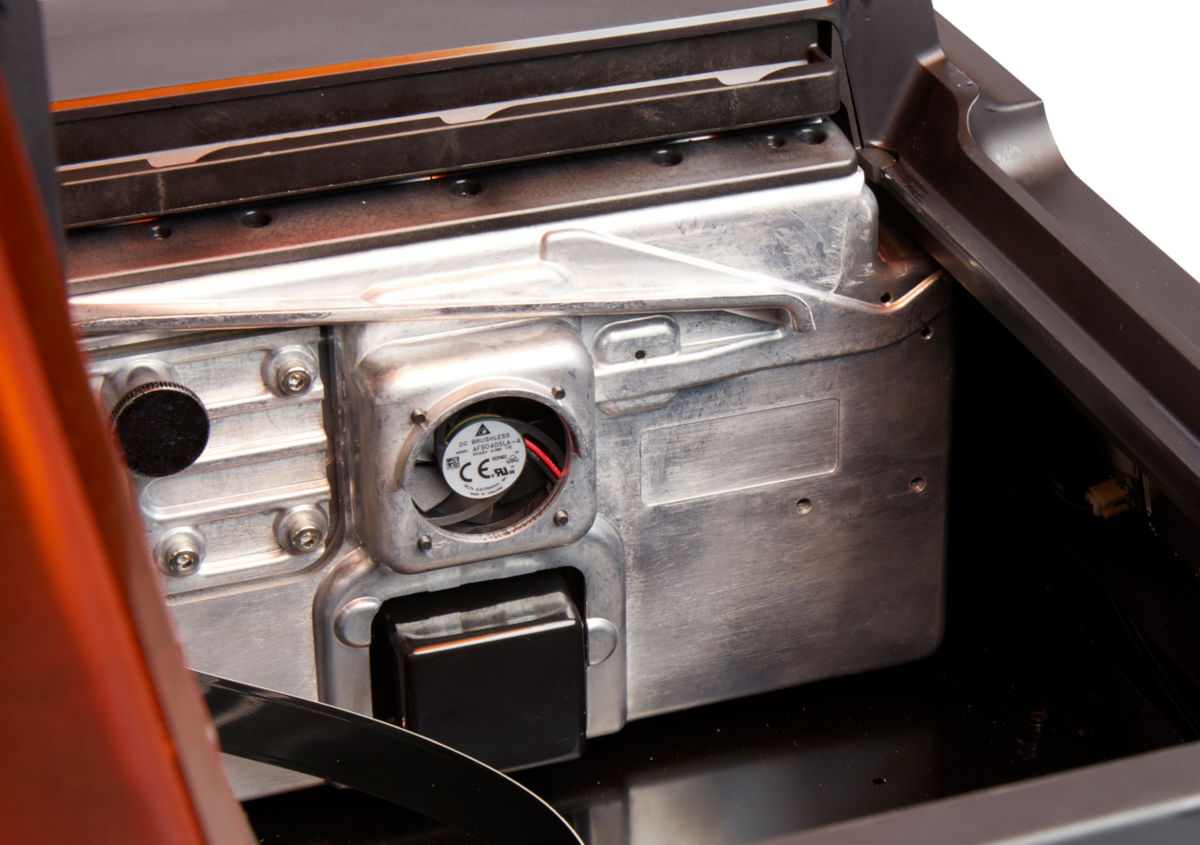
The Light Processing Unit (LPU) housing has a shipping latch that must be installed before shipping the Form 3. This prevents damage to the LPU and the optical components it contains.
The shipping latch is removed during the initial printer setup. If you do not have the original shipping latch, contact Formlabs Support or your authorized reseller.
- Tap the wrench icon on the touchscreen to open the “Settings” menu. Find and select the shipping option to prepare the printer for shipping.
- Unplug the printer.
- Open the cover and locate the shipping latch mounting points on the left side of the LPU housing. The LPU housing is in the LPU garage on the right side of the printer.
- Align the two slots in the latch with the two screw holes in the side of the LPU housing. The short side of the latch should be oriented away from the front of the printer and point outwards from the LPU housing.
- Loosely thread the two thumb screws through the slots and into the LPU housing.
- Slide the latch toward the front of the printer so that it engages with the inside of the printer shell. If necessary, adjust the position of the LPU by manually turning the lead screw at the back of the printer cavity. The shipping latch should lay flat against the LPU housing when it engages with the slot in the printer shell.
- Tighten both thumb screws to secure the latch. The latch does not move when both thumb screws are tightened.


Wrapping the printer
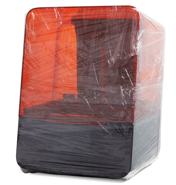
Securely wrap the seam between the printer’s top cover and lower shell to maintain alignment in transit. Wrap with plastic wrap multiple times horizontally and vertically so the entire printer is covered and the cover is firmly stabilized.
Packing the printer
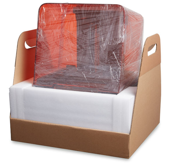
- Place the upright printer into the lift tray.
- Use the handles to gently place the lift tray and printer into the box.
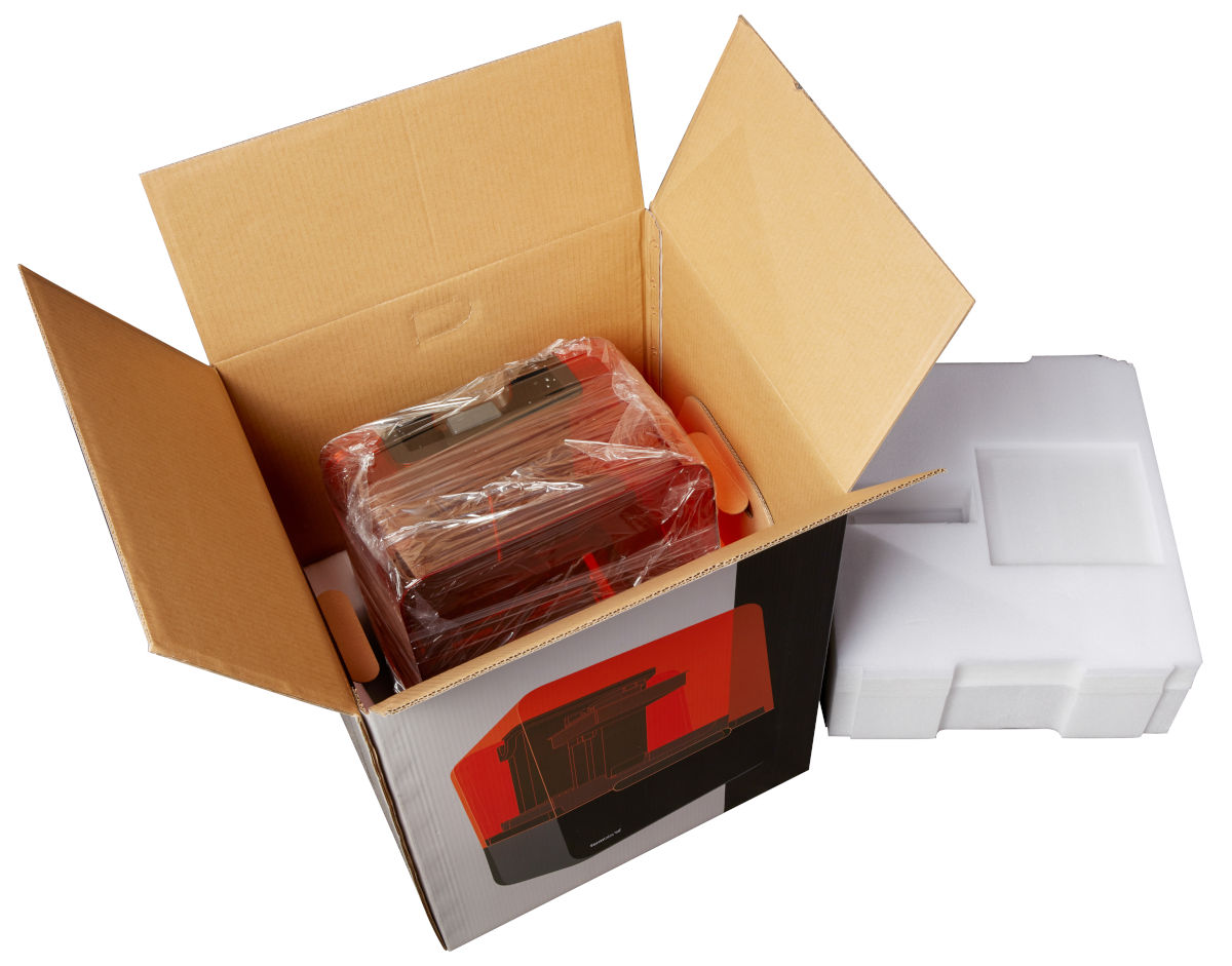
- Install the foam upper insert with the smaller voids facing upward. The foam should fit exactly around the top of the printer’s cover.
- Close the box, making sure that the printer and foam packaging fit entirely within the box.
- Seal the edges of all box openings with adhesive packing tape.
Published date:24-Jun-2019.
Maintaining the resin tank (Form 3)
This article applies to Form 3
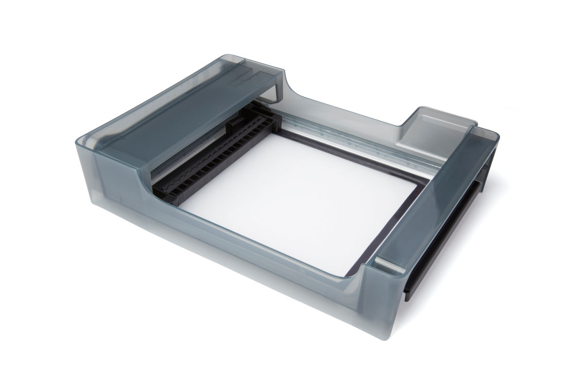
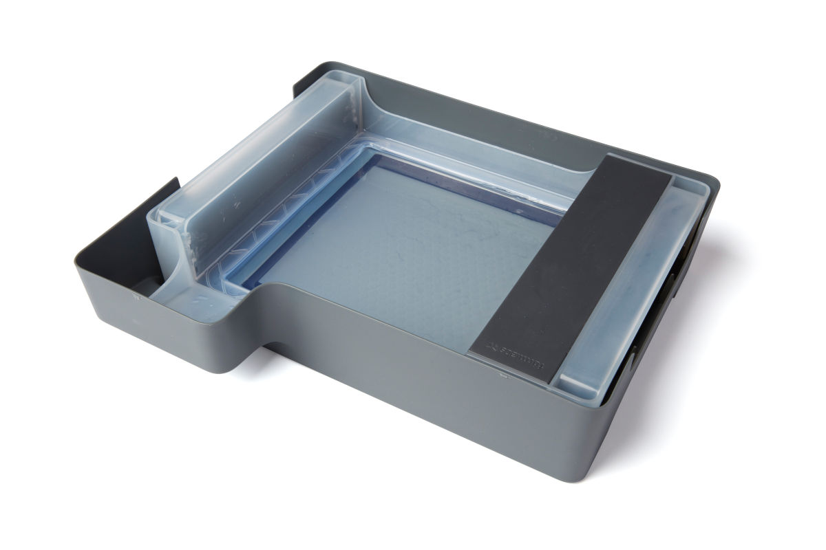
The Form 3 resin tank is the primary container for holding resin after it is dispensed from the cartridge. Resin is cured onto the build platform when the laser passes through the tank's bottom film. Be sure to handle and maintain the tank properly between each print.
Caring for the resin tank
Maintain and clean each resin tank using Formlabs instructions to maximize tank performance and to ensure consistent, high-quality prints over a tank’s lifetime. Only use approved materials and processes to clean the resin tank and film.
Check that the resin tank is in good condition between prints and before storing the resin tank in the tank case.
Resin tanks are consumables and require replacement. Expect to replace a Form 3 resin tank when wear on the film begins to affect print quality or when the printer is no longer able to properly tension the film.
Notice:
- Resin may spill over the tank walls if the resin tank tilts more than 5–10°. Hold the resin tank level with two hands. To inspect and clean the underside of the tank, empty the resin tank and take care to avoid spilling resin outside the tank.
- Sharp and metal tools can damage the dual-layer film in the resin tank and affect print quality. Do not use sharp or metal tools in the resin tank. Use only the tank tool to clean the inside of the resin tank.
To inspect the resin tank interior:
- Use the tank tool to inspect the resin and the film.
- Check for the following issues that may lead to print failures or any excessive wear that requires replacing the tank:
- Cured resin on the film
- Debris or failed prints in the resin
- Punctures, cuts, or gouges in the film
- Excessive “clouding” or wear in the film
- Check that the mixer and float are properly installed in the tank case.
- Follow cleaning instructions to remove cured resin, failed prints, debris, and settled pigment. For moderate wear or scratches on the film, use “Layout” in PreForm to print outside the worn or scratched area. If excessive wear or scratches on the film are affecting print quality, replace the tank.
To inspect the resin tank exterior:
- Visually inspect the film on the underside of the tank for fingerprints, dust, contamination, and scratches. Any of these can diffuse the laser light and lead to print failures or inaccuracies.
- Follow cleaning instructions to remove any fingerprints, dust, or contamination on the film before printing.
Storage
When changing resin types, always change both the tank and the cartridge. Remove the cartridge before removing the tank to prevent the cartridge valve from dripping resin into the printer interior. Use a different resin tank for each type of Formlabs resin. Cleaning the resin tank to change resins is possible, but may lead to contamination and print failures.
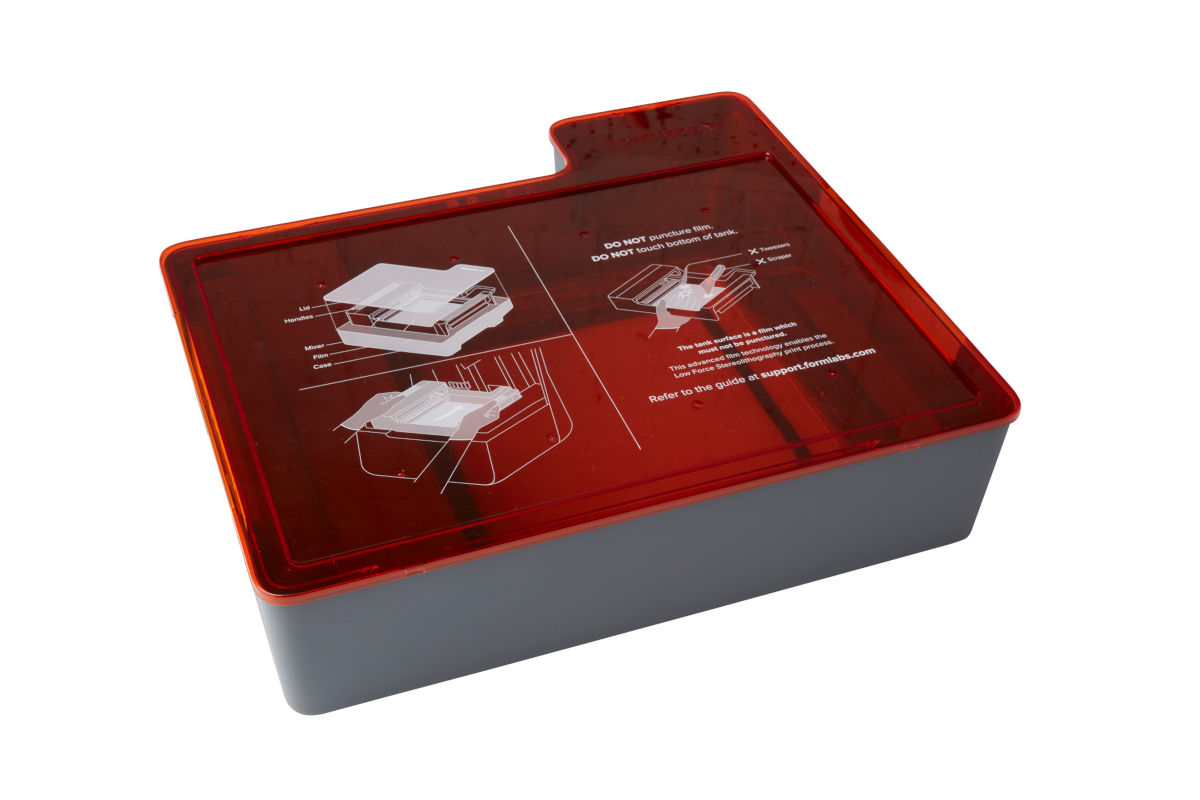
Whenever a resin tank is not installed in the printer, store it in its case. If the inside of the tank case or the bottom of the resin tank have liquid resin on them, clean them before storing the tank. Keep the case covered to prevent ambient light from curing the liquid resin in the tank.
Tip:
Label the tank and tank case to track the type and age of the resin in each tank.
Cleaning the resin tank
Keep the resin tank—especially the top and underside surfaces of the film—clean and free of cured resin and other debris to ensure print quality and extend the lifetime of the printer.
Warning:
Resin may cause skin irritation or an allergic skin reaction. Wear gloves when handling liquid resin or resin-coated surfaces. Wash skin with plenty of soap and water.
Protecting the ID chips on the resin tank and resin cartridge
The printer uses an identification (ID) chip on the resin tank to detect, track, and match the resin type in the tank with the proper resin cartridge. The ID chip is on the underside of each tank frame.
Protect the ID chips, the tank carrier, and the tank spring fingers from resin contamination or damage. Cured resin or contamination prevents the printer from properly identifying a resin tank during insertion or use. Avoid exposing the resin tank ID chip, the tank carrier, and the tank spring fingers to liquid resin.
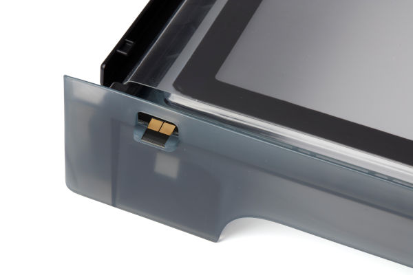
To remove resin from the ID chip or spring fingers:
- Apply a small amount of clean IPA to the tip of a cotton swab.
- Rub the tip of the cotton swab onto the silver pads on the ID chip or onto and around the spring fingers. The cured resin or contamination dissolves.
- Ensure that any IPA on the ID chip dries completely before continuing printing.
Notice:
Do not bend the spring fingers when cleaning.
Cleaning after a failed print
Printing with clean resin that is free of debris helps avoid print failures, which may damage the tank. A failed print may leave small, partially-cured pieces of resin floating in the tank or hard cured resin stuck to the film in the base of the tank. Inspect the tank after every print. Remove debris and clean the tank after a failed print.
Cleaning the resin tank exterior
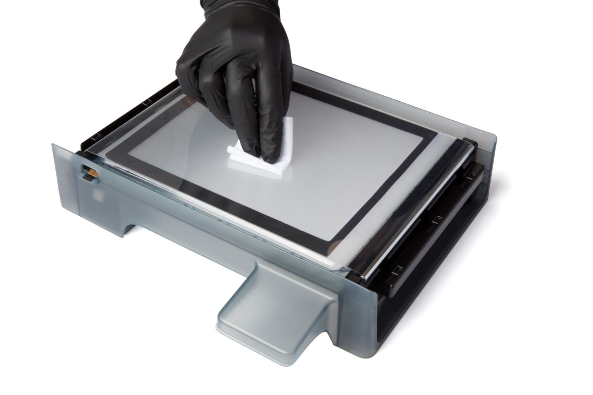
To clean the underside of the protective film:
- Empty the liquid resin from the resin tank into an opaque container.
- Place the empty resin tank upside-down on a clean, flat surface.
- Apply a small amount of clean IPA to a PEC*PAD.
- Wipe the surface of the film to remove contamination or resin.
Notice:
Do not allow liquid resin to become caught or to cure between the two layers of the tank film. Resin trapped between the film layers renders the resin tank unusable.
To clean the resin tank frame exterior:
- Use a paper towel to clean resin from the exterior of the tank frame.
- Keep the sides of the tank clean and free of resin.
- Avoid resin on the underside of the film, because the contamination may result in print failures and/or damage to the roller holder.
Disposing or replacing the resin tank
Replace the resin tank when wear on the film begins to affect print quality.
To replace the resin tank:
- Remove the build platform.
- Hold the side walls of the resin tank.
- Gently pull the resin tank upward and away from the printer to release the tank from the tank carrier.
- Store the resin tank in the tank case with the lid installed.
- Insert the new resin tank.
To dispose of a resin tank:
- Remove the resin tank.
- Transfer or dispose of the remaining resin.
Notice:
Pouring resin back into the original cartridge may risk contaminating the cartridge with cured resin pieces or debris, which can cause print failures.
- Use a paper towel to wipe any remaining resin off the old tank.
- Place the old tank in sunlight (such as on a window sill) or UV light to cure excess resin.
- Properly dispose of the tank once the resin is cured.
Published date:15-Jul-2019.
Cleaning after a resin spill
This article applies to Form 3
Occasionally, a print may fail to complete. Failed prints often leave small, partially cured pieces of resin floating in the tank or hard cured resin stuck to the flexible film at the bottom of the tank. Before a new print is started, the resin tank must be completely cleaned and cleared of debris. For best results, inspect and clean the tank after every print.
Warning:
Resin may cause skin irritation or an allergic skin reaction. Wear gloves when handling liquid resin or resin-coated surfaces. Wash skin with plenty of soap and water. Do not wash skin with products containing alcohol, like hand sanitizer, or any other solvents.
Removing cured resin manually
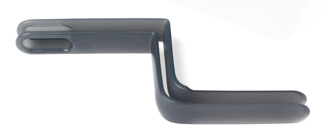
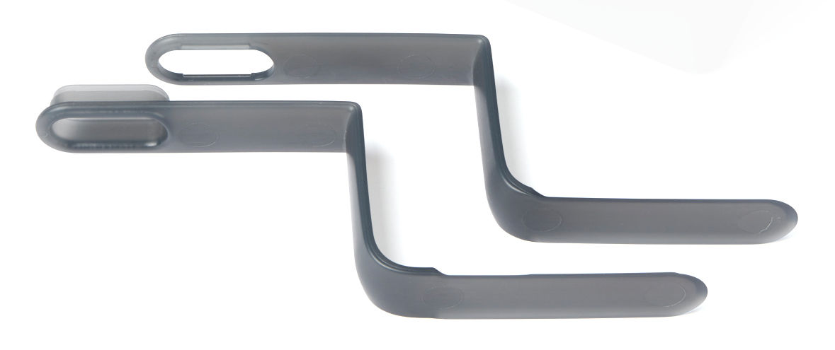
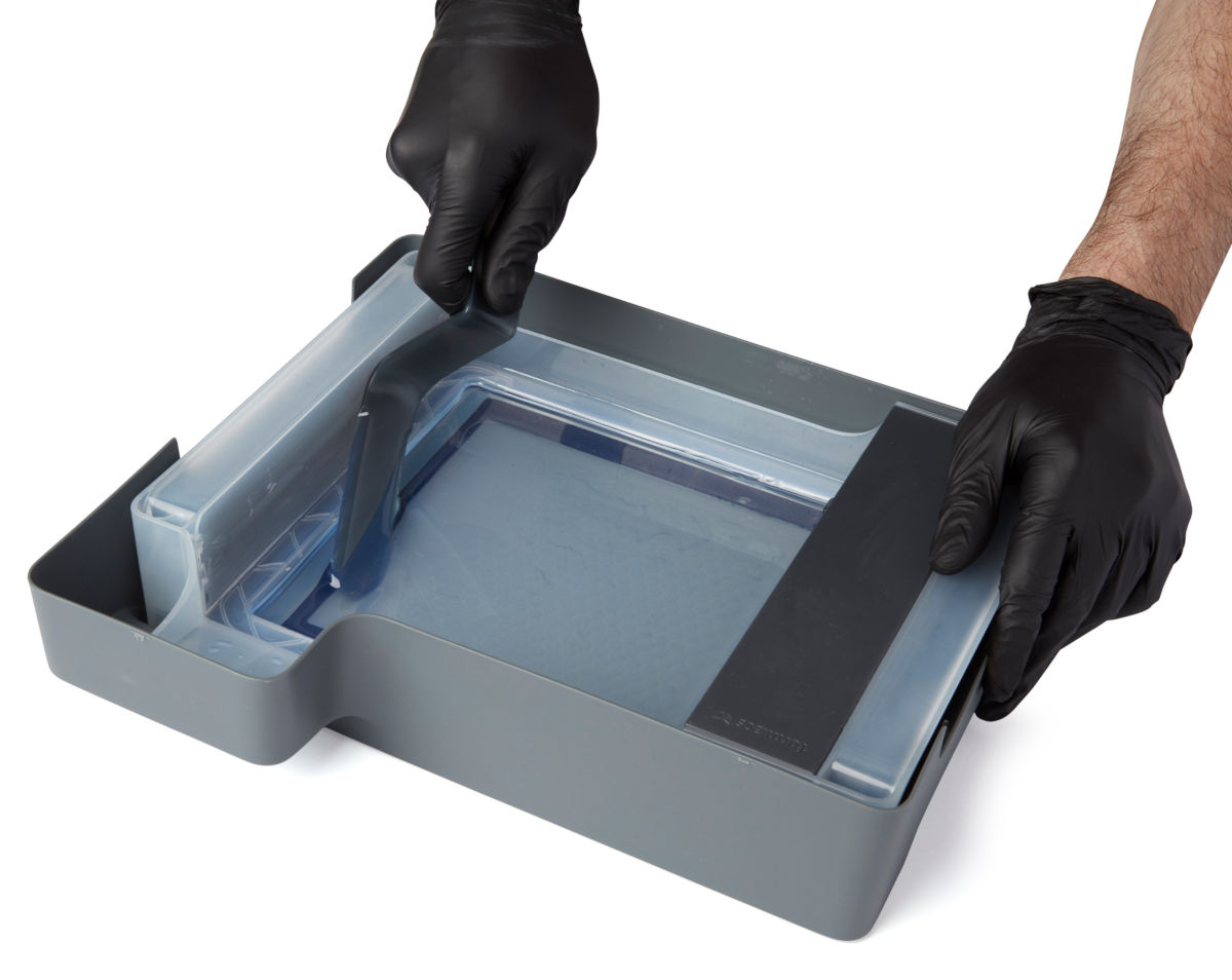
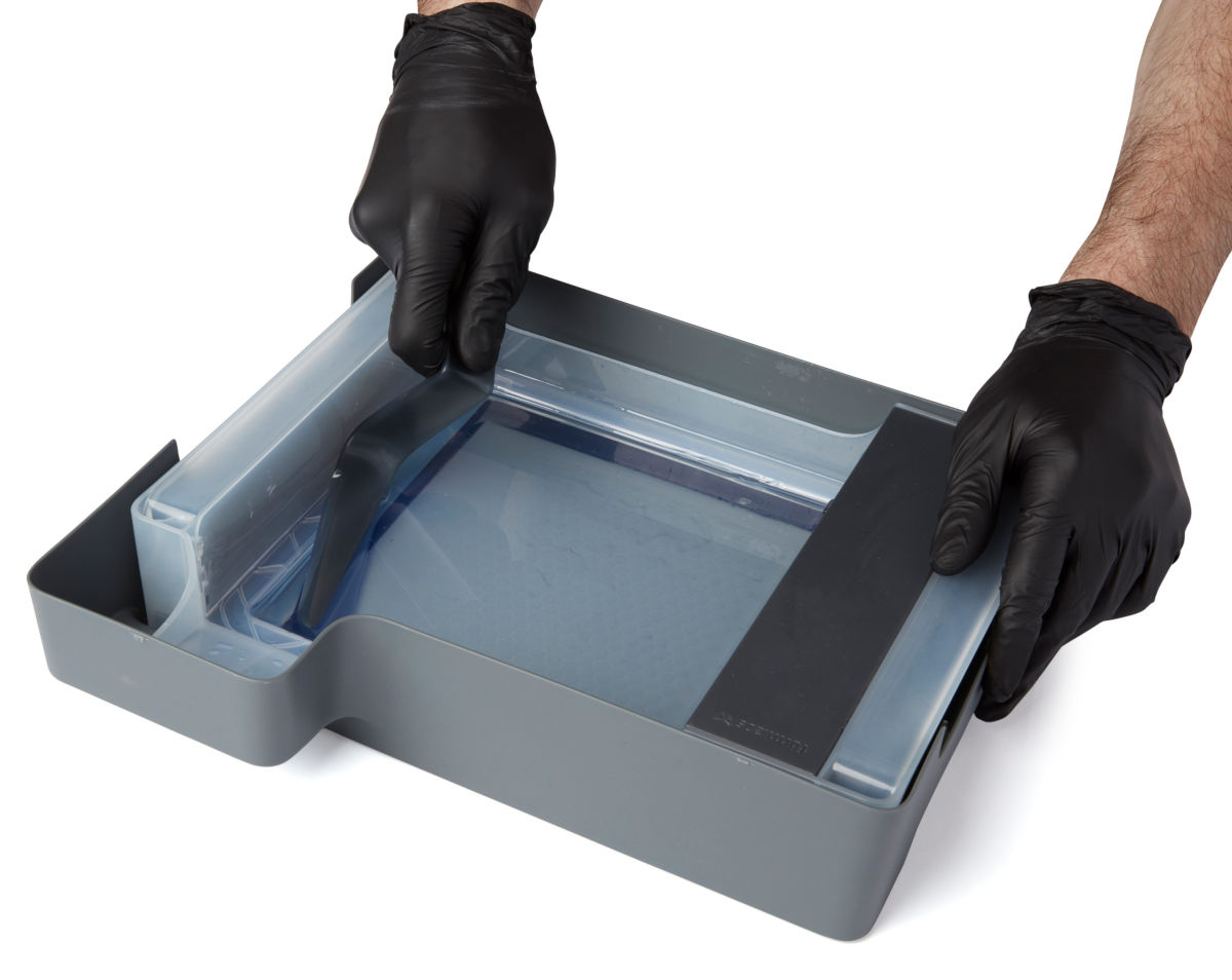
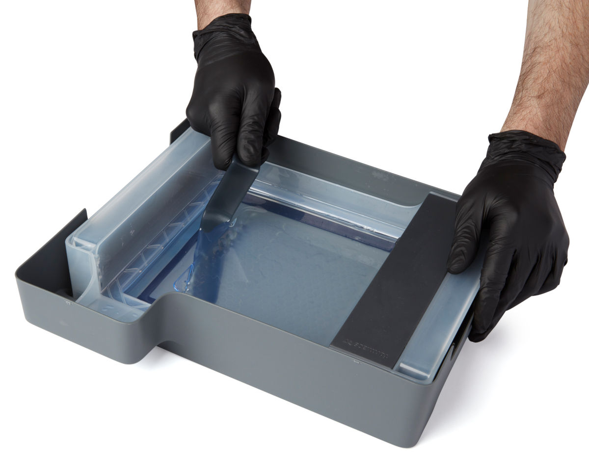
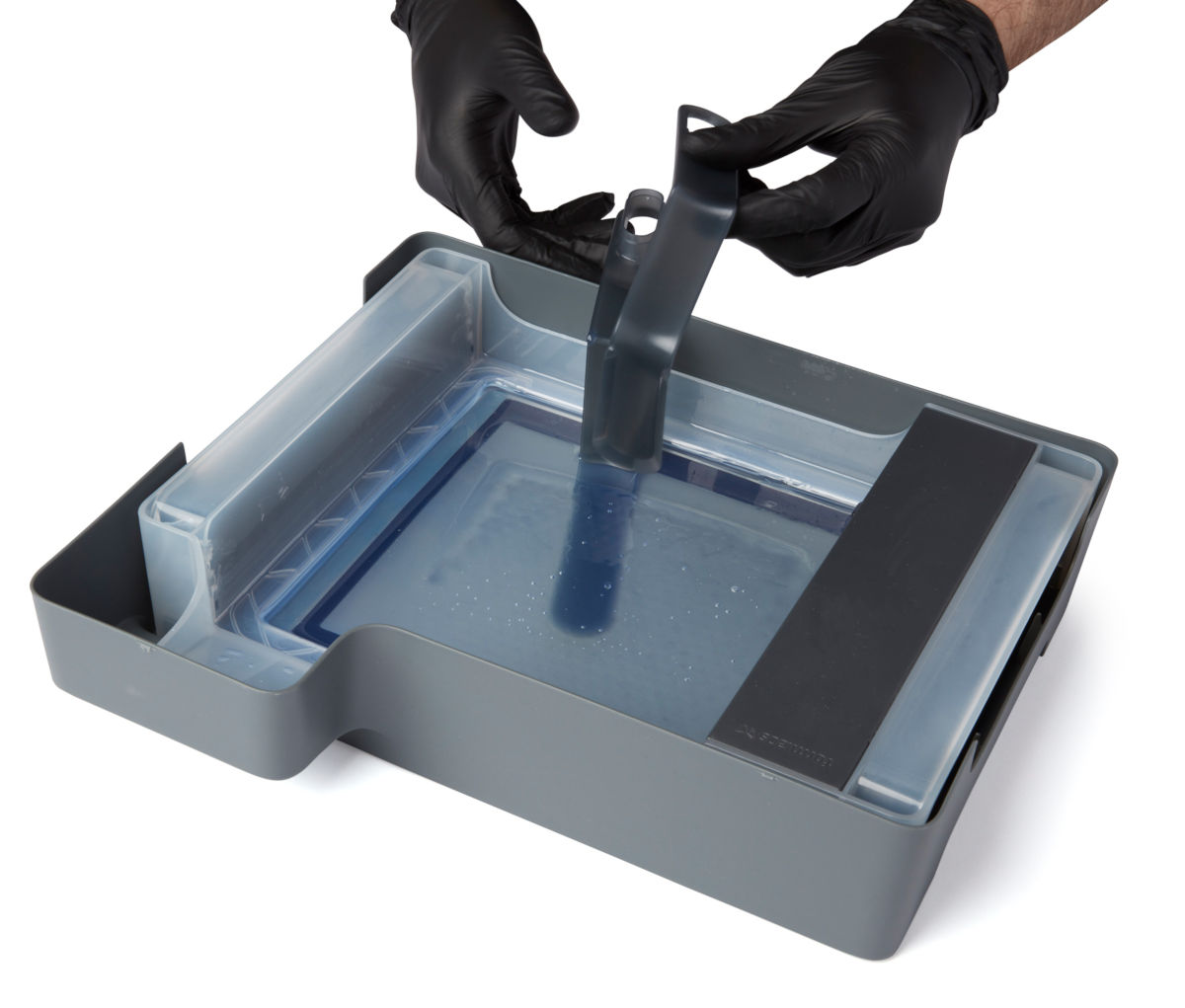
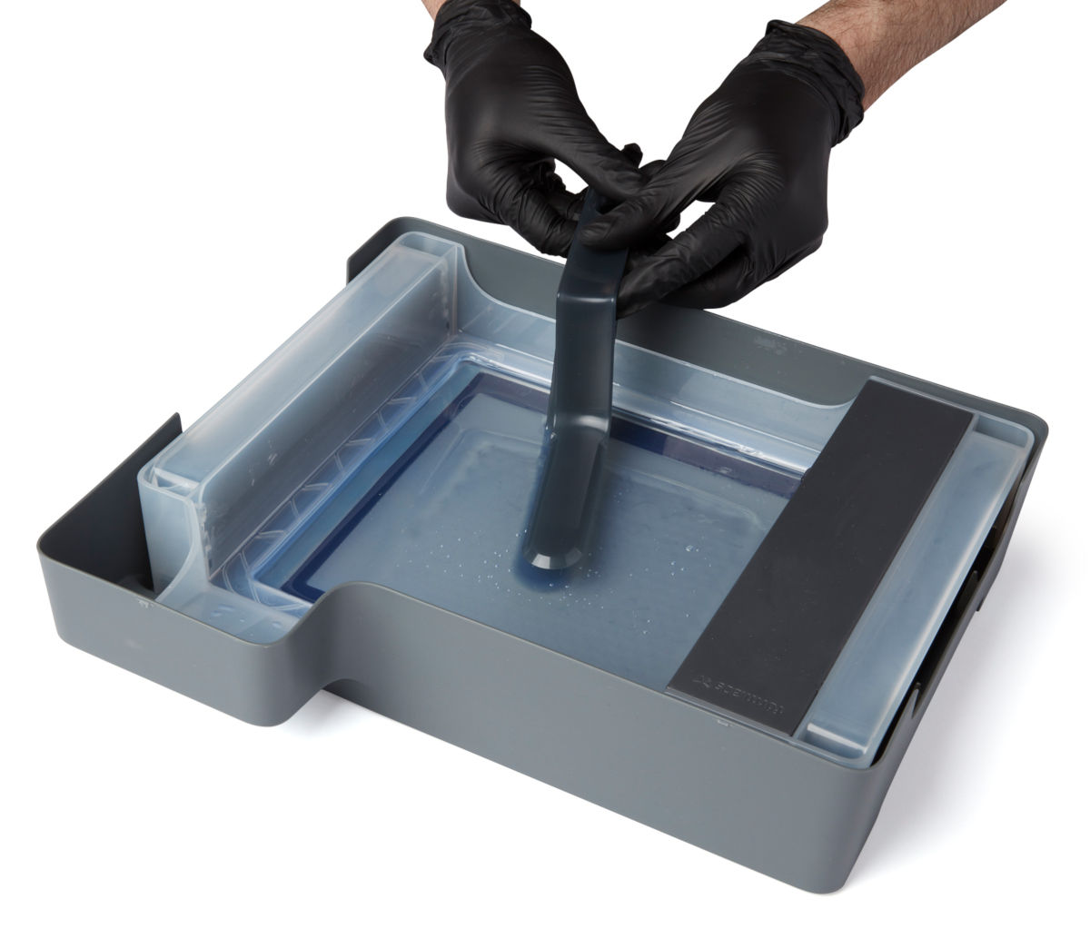
The Form 3 comes with a tank tool, which is a custom two-part scraper and tweezers. The tank tool is made of plastic and has rounded edges to protect the film at the bottom of the tank. Remove individual pieces of cured resin from the tank with the tank tool.
Notice:
Do not use the part removal tool, scraper, flush cutters, or any other metal tool to inspect the Form 3 resin tank or remove cured resin from the tank. Such tools may damage the tank film, leading to failed prints and/or a resin spill.
- Remove the build platform and resin cartridge first to avoid dripping uncured resin into the printer cavity.
- Remove the resin tank and place it in its case on a clean, flat surface. This allows for better visibility and more space to work than leaving the tank in the printer.
- Separate the two halves of the tank tool.
- Use the lower piece of the tank tool to scrape cured resin off of the film.
- Scrape laterally using the long side of the tool to get its edge under the cured resin.
- Continue scraping or twist the tool to lift the resin off of the film.
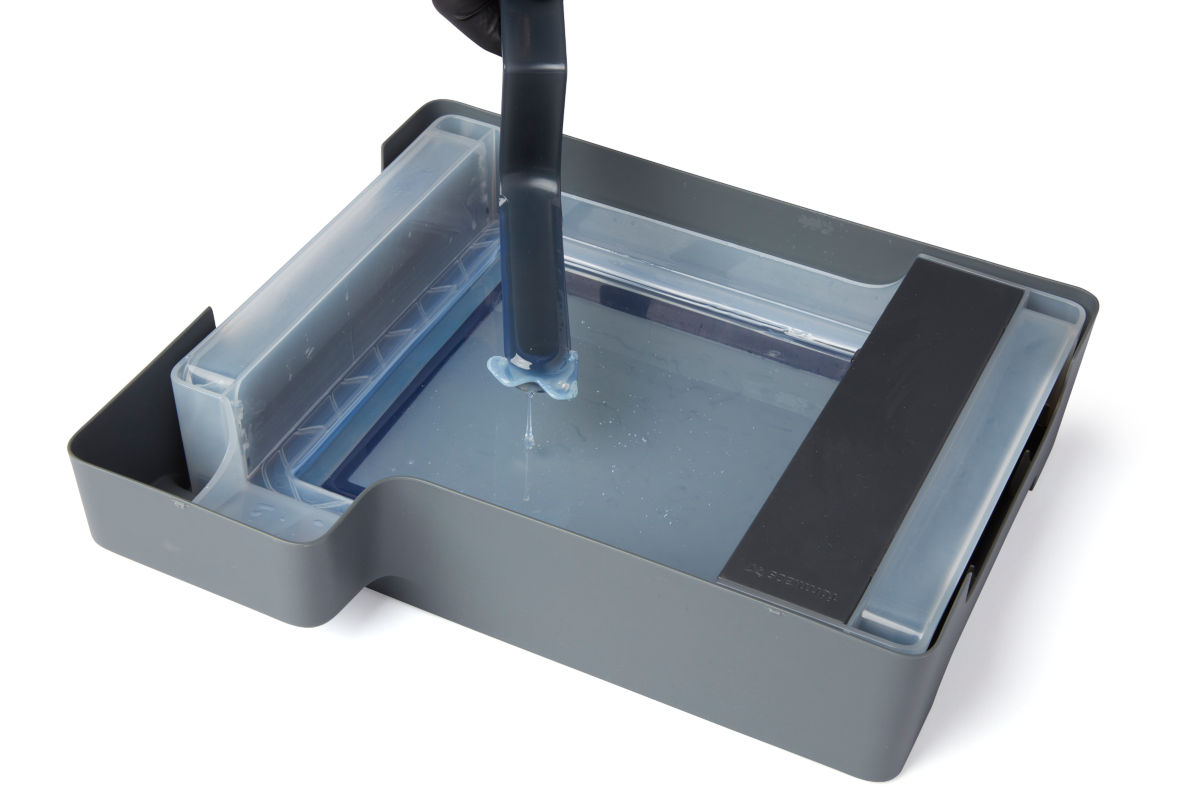
- If the cured resin is difficult to remove with one half of the tank tool, snap the two halves of the tank tool back together and use it as a pair of tweezers to grab floating pieces of cured resin.
- Scrape the film using the edge of the lower half of the tool, then press the top half down onto the cured resin to lift it out of the tank.
Cleaning the tank tool
Clean the tank tool after each use to remove excess liquid resin and prevent contamination.
To clean the tank tool by hand:
- Apply clean IPA to a clean paper towel.
- Wipe the surface of the tank tool to remove resin.
- Allow the tank tool to air dry.
To clean the tank tool using the Form Wash:
- Rest the tank tool in the Form Wash basket.
- Set Form Wash to clean for 5 minutes. Increase the wash time for heavily-used solvent.
- Allow the tank tool to air dry after washing.
Filtering the resin (optional)
After removing the primary print failure, inspect the resin and tank for other small fragments. While the mixer will help keep the print area clear during printing, clean resin and optical transparency in the bottom of the resin tank are always the best way to ensure quality prints.
Notice:
If you see or feel any resin cured in your tank, it's essential to remove debris by cleaning the tank or the next print will fail. Use a paint filter with a "Fine" or 190 micron mesh size to thoroughly strain liquid resin.
Reseating the mixer
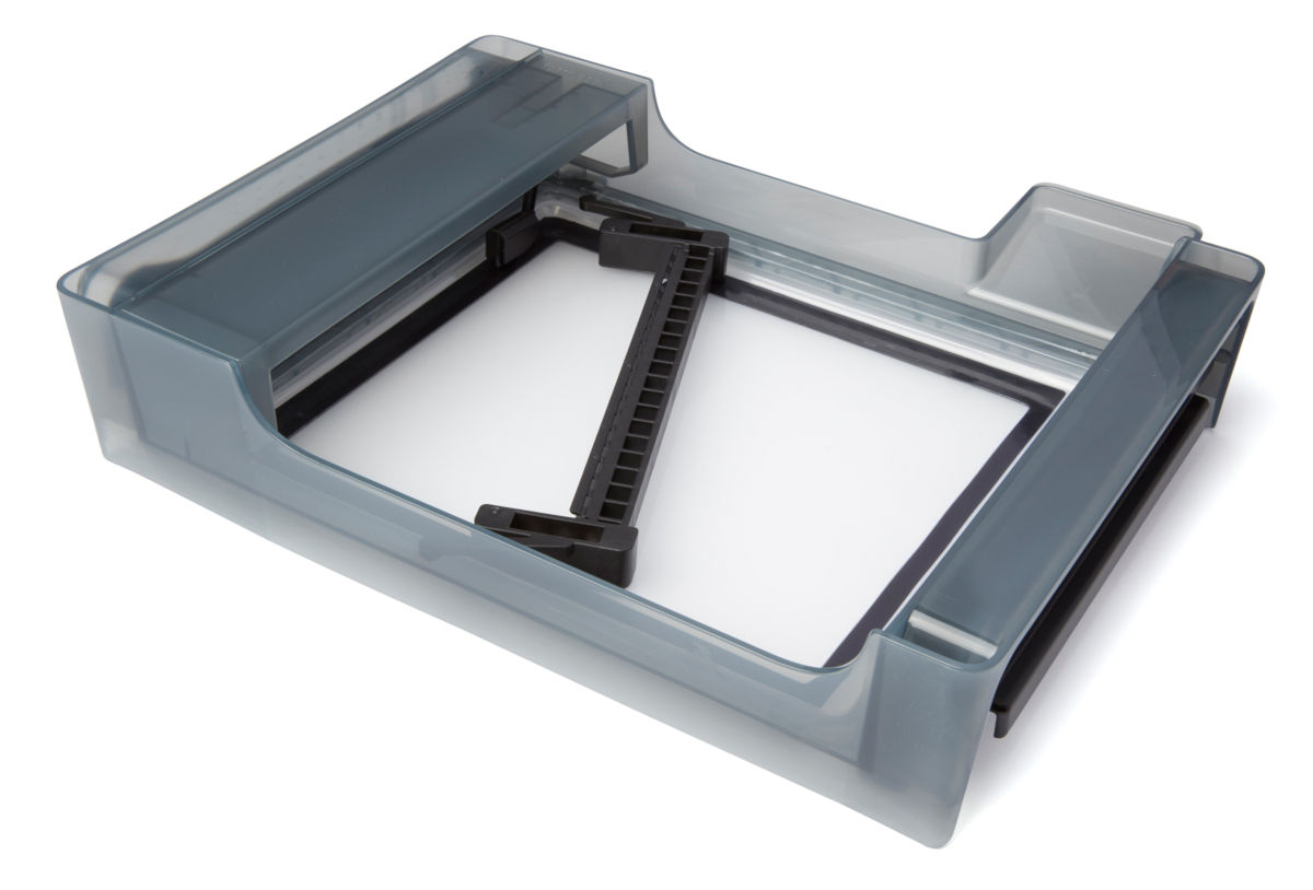
At the start of each print, the LPU housing pulls the tank mixer back and forth across the tank film several times. This motion mixes the resin in the tank while also checking for cured resin on the film and on the build platform. If the mixer encounters cured resin blocking its path, its magnets will decouple from the magnets in the LPU housing and the printer will pause the print. This is the designed behavior of the mixer and is intended to protect the tank film and prevent further print failures.
- Open the printer cover.
- ush the mixer back into its home position on the left of the tank.
- Orient the mixer with the arms facing left.
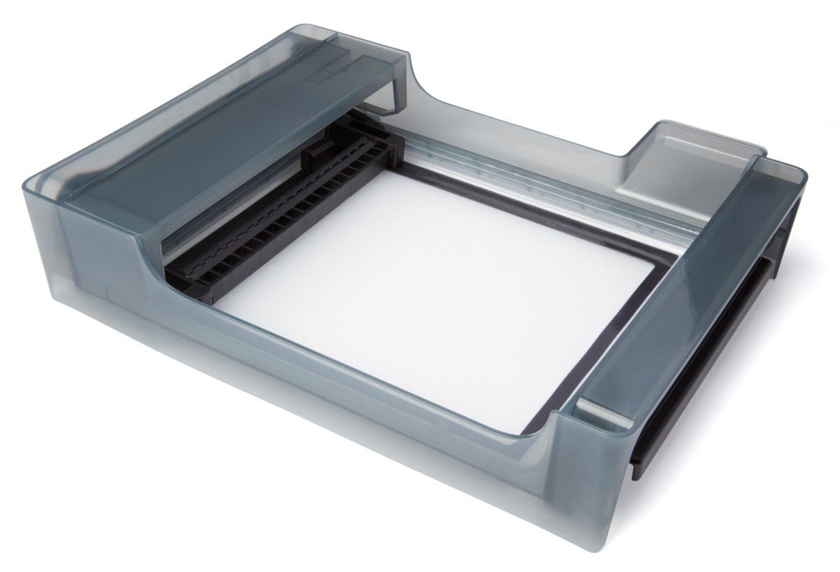
- Slide the mixer left until the arms click into place.
- Inspect the film using the tank tool.
Published date:24-Jun-2019.
Cleaning the glass optical window (Form 3)
This article applies to Form 3
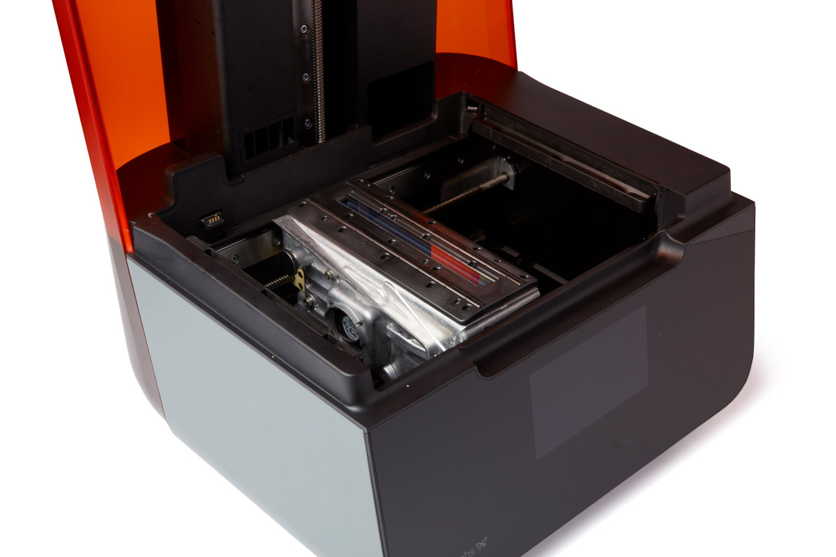
In the Form 3, the printer optics - the laser diode, mirrors, and other components - are contained in a module called the Light Processing Unit (LPU). The LPU, sitting inside the LPU housing, moves left and right in the printer during each layer of a print. The laser beam exits the LPU through an anti-reflective coated glass optical window mounted on top of the unit. The window preserves print quality and reliability by protecting the LPU components from dust, oil, and resin contamination. Keep the glass optical window clean to ensure successful prints.
The LPU housing, with the LPU, rollers, and optical window, sits in the LPU garage on the right side of the printer when a print is not running. The garage protects the optical window from most forms of contamination, but dust can still accumulate on its surface over time. As the laser passes through the optical window, any such contamination can cause the laser light to diffuse or weaken, resulting in print defects.
Tip:
If you notice dust or contamination on the underside of the optical window or inside the LPU, contact Formlabs Support or your authorized reseller for additional instructions.
Overview
To maintain the glass optical window, inspect the optical window surface for dust, oil, or contamination using a flashlight, LED, or cell phone light. If dust, oil, or contamination is noted, clean the glass surface following Formlabs instructions. As with most optical surfaces, minimal cleaning is the best cleaning.
Tip:
To protect the optical window from dust, keep the Form 3 cover closed when the printer is not in use.
Required supplies
To remove dust:
- Nitrile gloves
- Flashlight, LED, or cell phone light
- Rubber bulb air blower
- PEC*PAD contaminant free wipes
To wet wipe:*
- Nitrile gloves
- Flashlight, LED, or cell phone light
- Rubber bulb air blower
- PEC*PAD contaminant free wipes
- 90% or higher isopropyl alcohol (IPA), non-recycled
* Wet wipe only if necessary after removing dust.
Estimated time: 10 minutes
Removing the consumables
Always remove the build platform, resin cartridge and resin tank before performing maintenance on the printer to avoid dripping resin into the printer cavity.
- Lift the platform lock and remove the build platform.
- Close the resin cartridge vent cap and remove the resin cartridge.
- Remove the resin tank from the printer. Place the resin tank in its case.
- Cover the resin tank case and set it aside with the build platform and resin cartridge on a clean, flat surface.
Inspecting the optical window
Inspect the optical window for dust, oil streaks, fingerprints, or cured resin.
Tip:
For best results, dim or turn off the main lights in the room when inspecting the optical window with a secondary light source. Always wear clean gloves when handling optical surfaces to avoid contamination. Do not touch the rollers next to the optical window to avoid contaminating them.
- With the printer plugged in and powered on, tap the wrench icon on the touchscreen to enter the “Settings” menu, then tap “Calibration,” then tap “LPU Replacement.” The LPU housing moves from its storage position on the right side of the printer into its maintenance position.
- When prompted by the touchscreen, disconnect the power cable before continuing with maintenance.
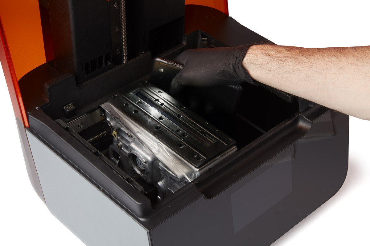
- Shine a secondary light source (for example, a flashlight, LED or cell phone light) onto the optical window to reveal any hidden contamination on the glass surface.
- Hold the light source at the shallowest angle possible. From the edges of all three accessible sides (that is, left, front, and right), scan the light back and forth across the optical window.
A properly illuminated glass optical window
Removing dust
Remove dust and other loose contaminants, which can interfere with the laser.
Tip:
Avoid using compressed air. If necessary, carefully follow the directions on the canister to avoid depositing propellant onto the glass surface. Propellant contaminates the optical window and can affect print quality.
- Use a rubber bulb air blower to gently remove any visible dust from the optical window.
- Make sure to remove any large particles that may scratch the glass surface.
- If a rubber bulb air blower is not available, compressed air may be used.
- Use a new PEC*PAD to remove any remaining dust from the optical window with a dry wipe.
- Wipe slowly, pulling the PEC*PAD toward you, repeating until you have cleaned the entire glass surface.
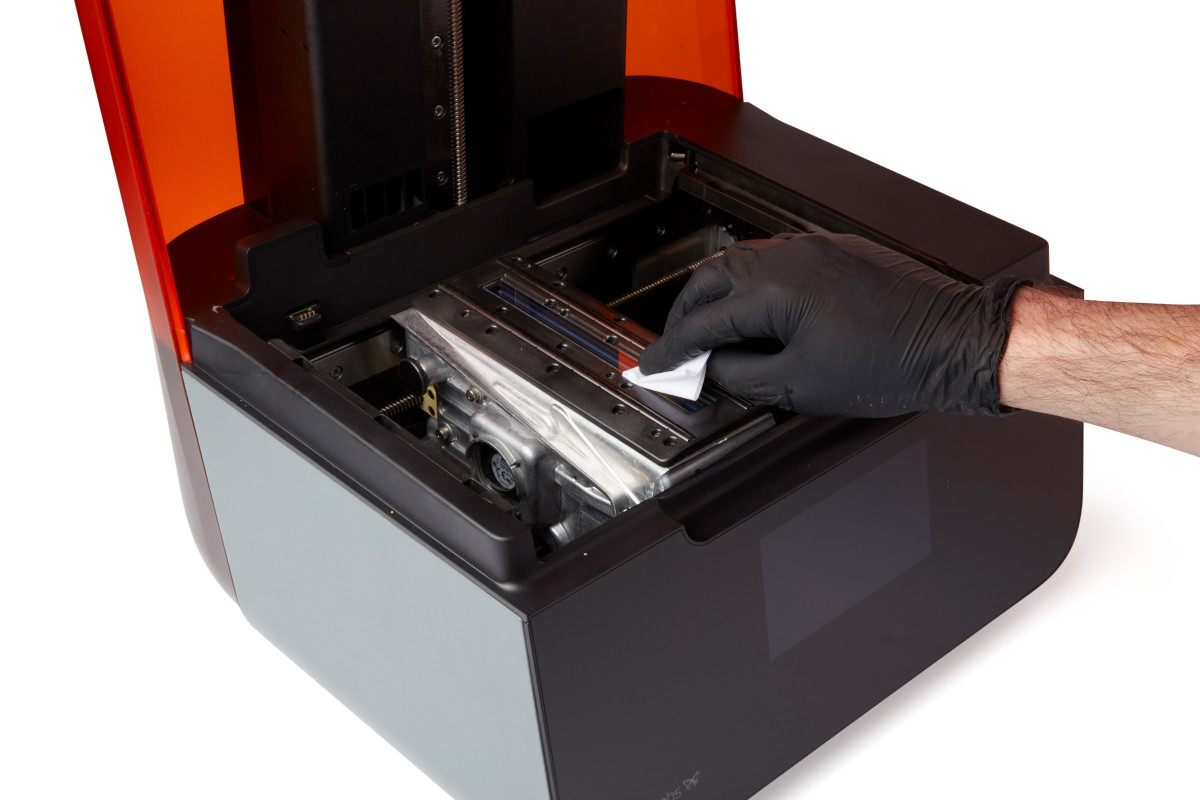
Proceed with a wet wipe only if the dry wipe does not clean the glass completely.
Notice:
Wiping the optical window with non-recommended materials may damage the glass surface and affect print quality.
Cleaning with a wet wipe
Tip:
If resin has dripped onto the window, use a small amount of IPA with a clean microfiber cloth first. Move the cloth slowly to allow the IPA to dissolve the resin. Allow the surface to dry before using additional IPA with PEC*PADs to wipe the glass surface.
Wet wipe the optical window only if oil, smudges, fingerprints, or resin contamination is visible. Only use IPA to clean the glass surface as any other cleaning solution may degrade the anti-reflective coating.
Notice:
Avoid using cleaners or materials that can scratch or leave residue on the anti-reflective glass surface of the optical window.
- Apply a small amount of IPA to a new PEC*PAD.
- Wipe the optical window slowly with the PEC*PAD, pulling the PEC*PAD toward you. Repeat this step until you have cleaned the entire glass surface.
- Use your secondary light source to inspect the optical window. Repeat the wipe if any streaks are visible.
- Multiple passes may be necessary to achieve a streak-free surface. Each PEC*PAD can be used multiple times by refolding the material to expose a fresh surface for each pass on the glass panel.
- Dry wipe the glass surface again with a new PEC*PAD to remove any remaining streaks.
If streaks are difficult to remove, contact Formlabs Support or your authorized reseller. When requesting help, please provide photos of the optical window illuminated by a secondary light source and a list of attempted cleaning steps.
Completing the maintenance
After cleaning the optical window, power on the printer to complete the maintenance process. Close the printer cover and connect the power cable to the printer and the power supply. The printer will initialize and the LPU will move back to its home position to perform a calibration.
Published date:24-Jun-2019.
Submitting a support request for failed prints
This article applies to Form 3
Before submitting a support request for failed prints, please perform these initial troubleshooting steps to help us process your request as quickly as possible.
As you go through these steps, note your results and include them in your next message to Formlabs Support or your authorized reseller.
TIP:
Check the expiration date of your resin. If it is close to its maximum shelf life, you should replace your resin before trying any of the following steps.
Cleaning the resin tank
Whether a tank is new or has already been used, an optically clear path for the laser beam is essential for printing. Before confirming a print, inspect the resin tank for markings or cured resin particles.
Form 3
- Inspect the resin tank for debris with the tank tool.
- Remove any failed prints and cured resin using the tank tool.
- Filter the resin to remove any contamination or cured resin.
- Inspect the flexible film at the bottom of the resin tank for scratches or wear. Excessive wear means the resin tank needs to be replaced.
- Inspect the underside of the flexible film for dirt, dust, or fingerprints. Clean it with Formlabs recommended steps and supplies.
TIP:
Keep resin tanks clean and well-maintained between prints for reliable and successful printing.
Checking the optical window
Form 3
The optical surface most likely to be contaminated is the glass optical window in the roller holder, which sits atop the Light Processing Unit (LPU).
- Tap the “Maintenance” option in the touchscreen menu. The LPU housing moves into its shipping position.
- Inspect the optical window on the Form 3 for contamination.
- Follow the instructions in Cleaning the glass optical window. If streaks are difficult to remove, contact Formlabs Support.
Notice:
Follow the optical surface cleaning guides exactly. Failure to follow instructions could damage the printer.
Running the test print
In order to introduce a known good variable to isolate any printing issues, you can run a Formlabs test print.
- Make sure your firmware and software are updated to the latest version.
- Print the Formlabs test print file in a standard Resin (models available for Clear, Grey, White, and Black) at 100 microns.
- Please regenerate the supports using all of the default values.
Photographing the test print
Make sure to take clear, focused photographs of your test print so Formlabs Support or your authorized reseller can best diagnose your issue. It is most helpful to see the following angles of your test print, both on the build platform and then fully dried and finished:

Side view of the supports and bases.

Top view of prints on the build platform.

45 degree close up of print details.
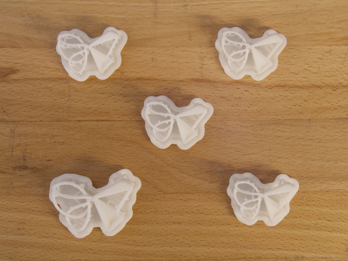
Top view of finished prints.
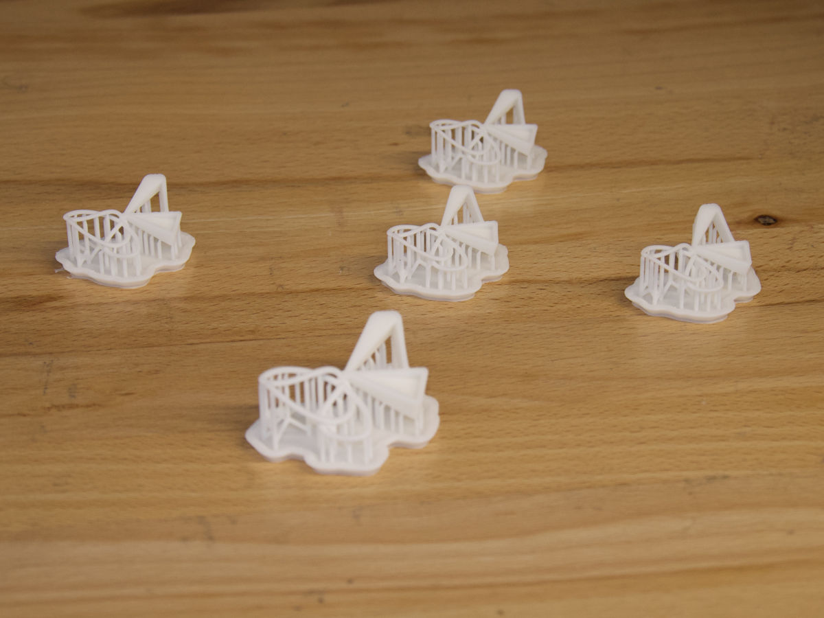
45 degree closeup of finished prints
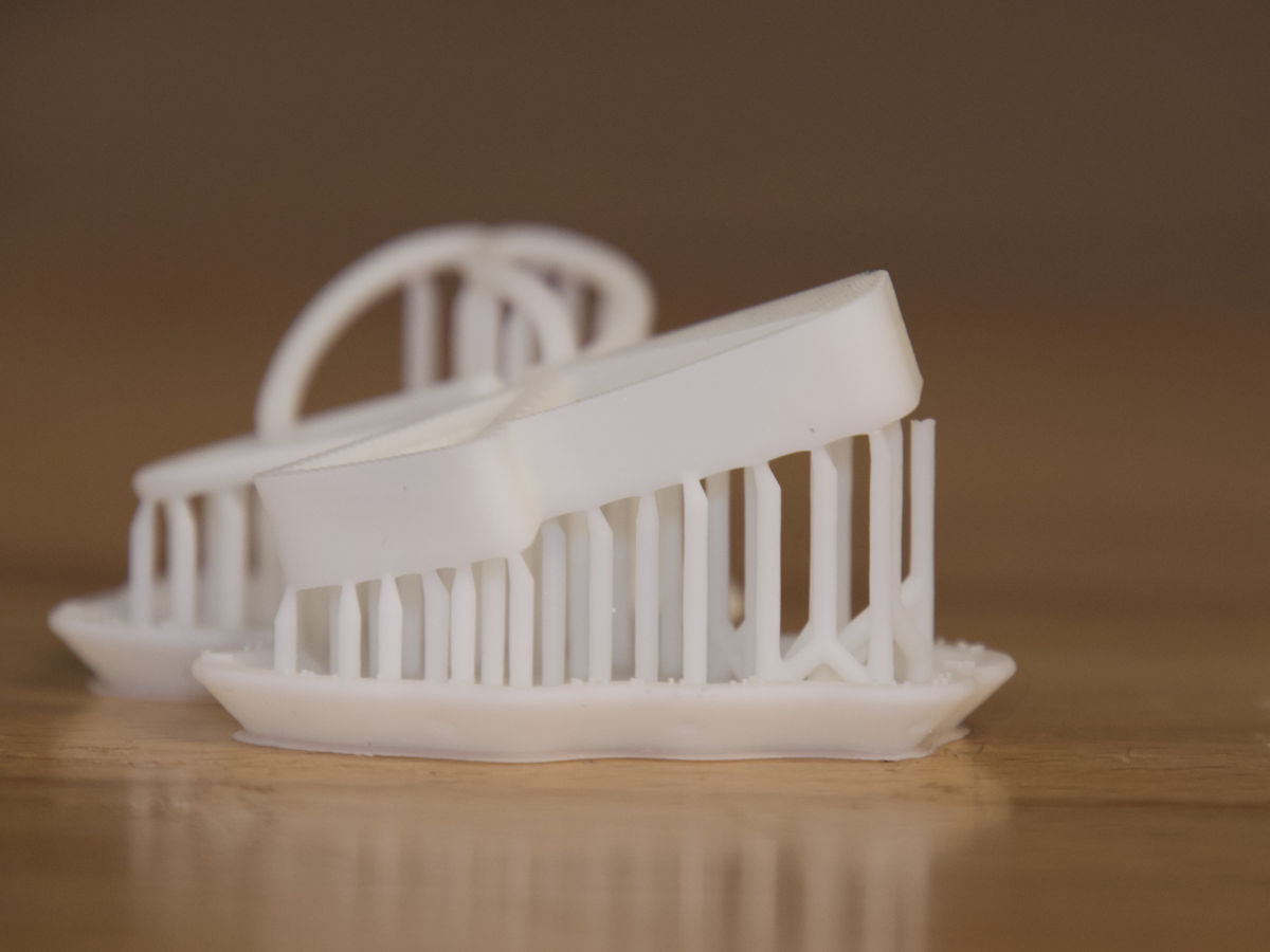
Close up of any specific print failures.
Submitting a request
After you have finished all of the troubleshooting steps, please submit the photos of your test print within a new (or current) support request to Formlabs Support or your authorized reseller, along with the serial name and original order number of your machine. If you have already submitted a request and opened a conversation, please include these additional photos while you wait for a response. You can also include photos of any print defects in the same focused, well-lit style of the test print photos.
Before or immediately after contacting Support, navigate to the printer's “Settings” menu, then select “Printer Info” and “Upload Diagnostic Info”.
Formlabs Support will get back to you within 24 hours (Monday–Friday) of receiving your message and information. Please allow additional time for requests that come in on weekends and holidays observed by our US and EU offices. Including the above information in your request will help us diagnose your printer’s issue and get you printing again as quickly as possible.
Published date:24-Jun-2019.
Product glossary (Form 3)
This article applies to Form 3
External components
Item/Description
Image
Shell:
Five protective external casings protect the printer’s internal components:
- (1) Rear shell: a plastic casing for the back of the printer.
- (2) Side shells: metal casings for the left and right sides.
- (1) Top shell: a plastic casing to protect the area surrounding the resin tank, under the cover.
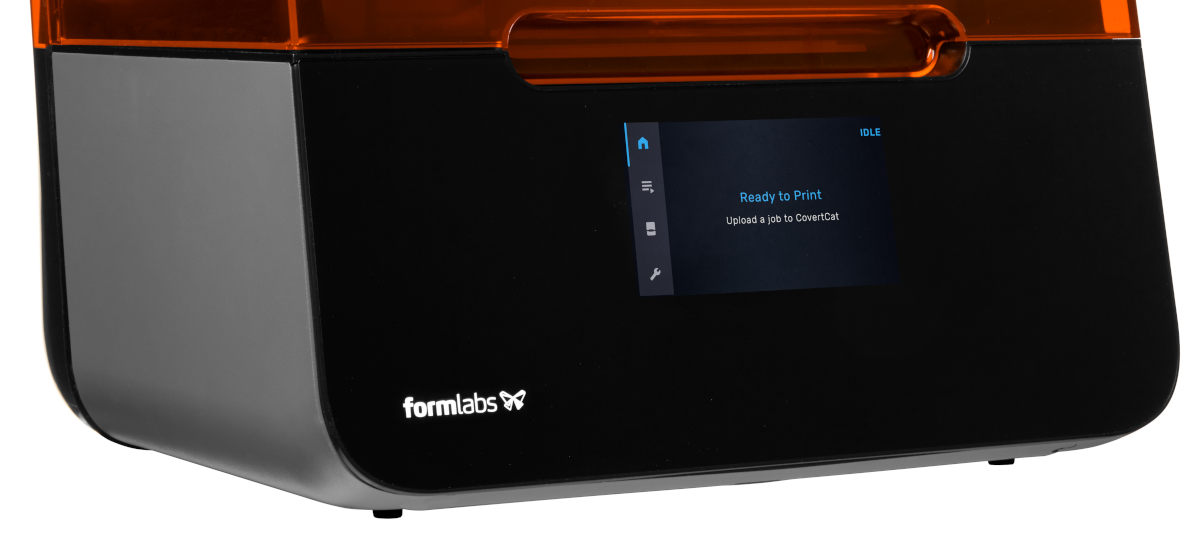
- (1) Front shell: the glass display assembly is attached to a plastic panel, which encases the front of the printer below the cover.

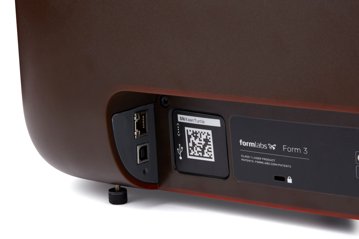
Leveling feet:
Each corner of the printer is supported by a rubber foot that is threaded into the bottom of the machine. When prompted by the touchscreen, use the leveling disc to raise or lower each foot to ensure that the printer is acceptably level.
Display assembly
Item/Description
Image
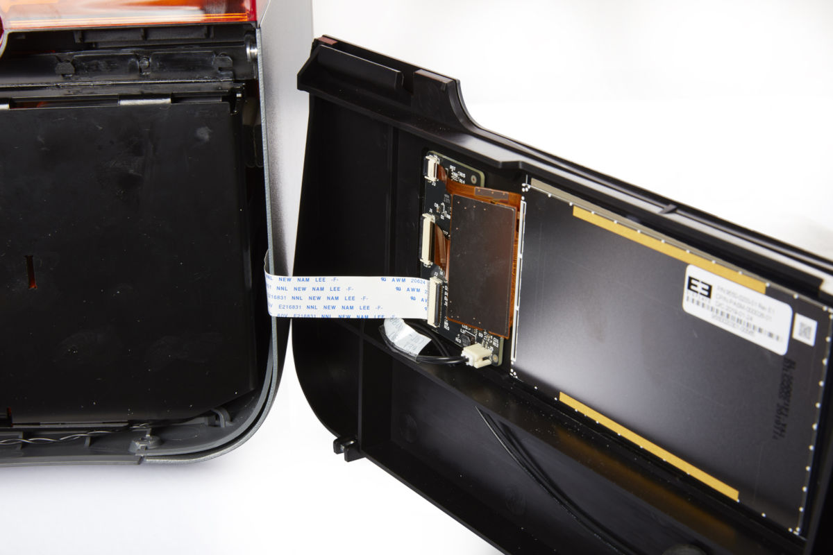
Display assembly:
The display assembly contains the touchscreen and the display circuit board. A ribbon cable connects the display assembly to the motherboard.
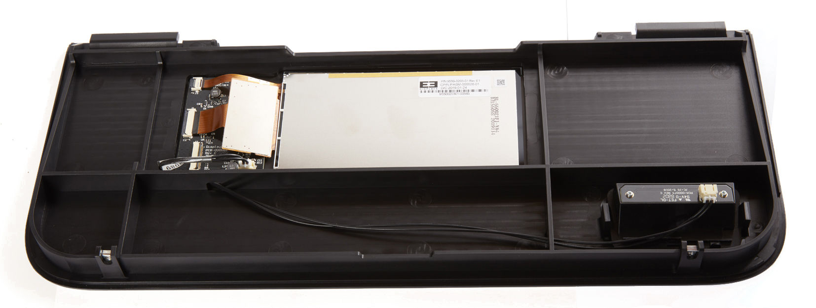
Touchscreen:
The LCD capacitive touch user interface displays print information, settings, and error messages.
Display PCB:
This circuit board, separated from the main motherboard, controls the touchscreen.
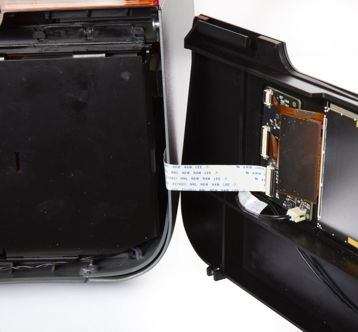
Display cable:
A flat, flexible cable connects the display assembly to the motherboard.
Cover
Item/Description
Image
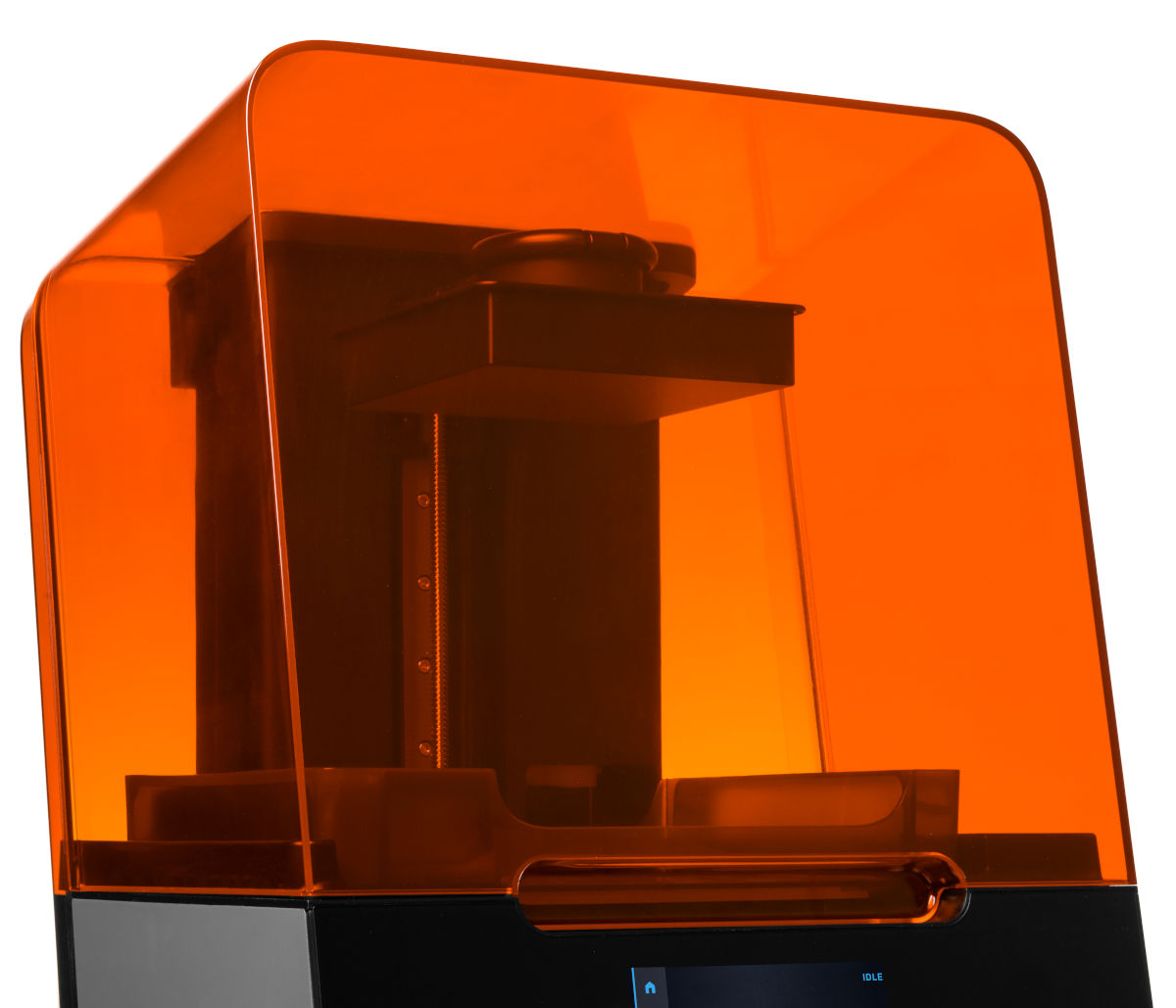
Cover:
The upper enclosure, made of strong, amber-tinted material, blocks exposure to the laser and protects the resin from curing due to ambient light.
Interlock magnets:
The interlock sensor detects these magnets to determine when the cover is closed. This safety mechanism triggers the "cover open" message on the touchscreen and disables the laser when the cover is open
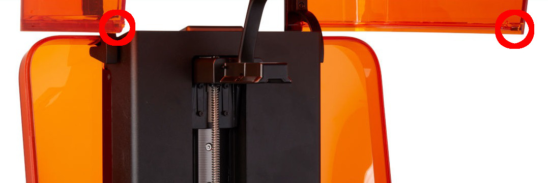
Cartridge
Item/Description
Image
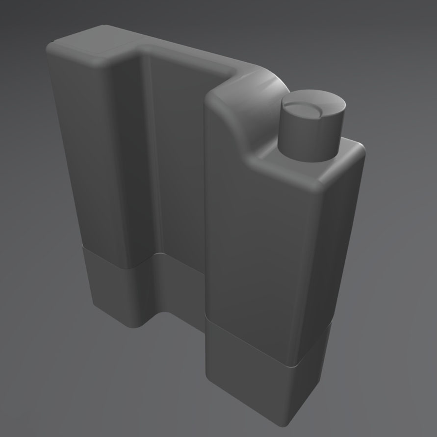
Cartridge:
This container holds the resin before dispensing into the resin tank. Shake the cartridge periodically to keep resin well mixed.
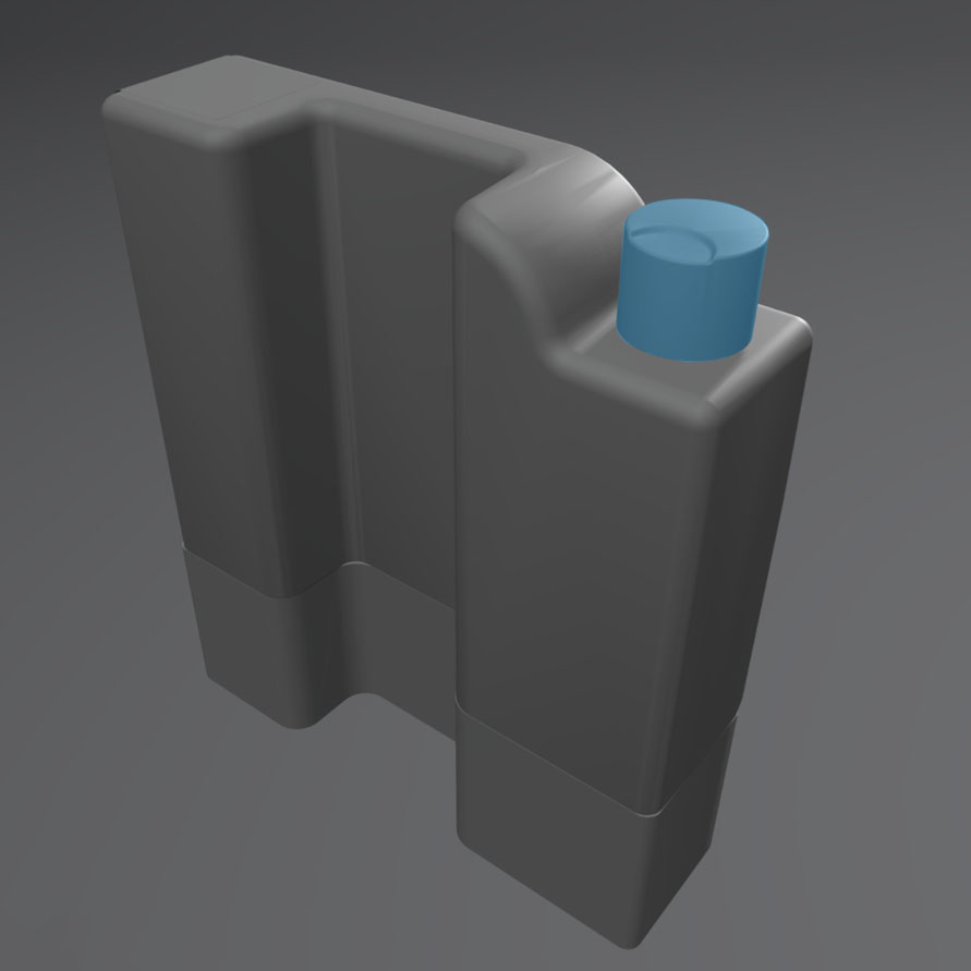
Vent cap:
The lid at the top of the cartridge allows for air interchange, enabling proper resin dispensing. Push the vent cap open prior to printing.
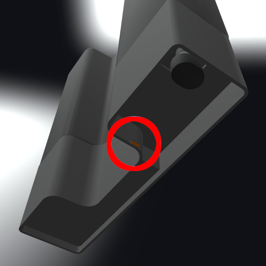
Cartridge ID chip:
An Electrically Erasable Programmable Read-Only Memory (EEPROM) chip is attached to the cartridge skirt and is programmed with the resin type. This chip communicates to the printer via spring fingers on the cartridge floor.
Bite valve:
This flexible seal regulates resin dispensing. Resin flows out when the cartridge dispense arm squeezes the valve open.
Cartridge floor assembly
Item/Description
Image
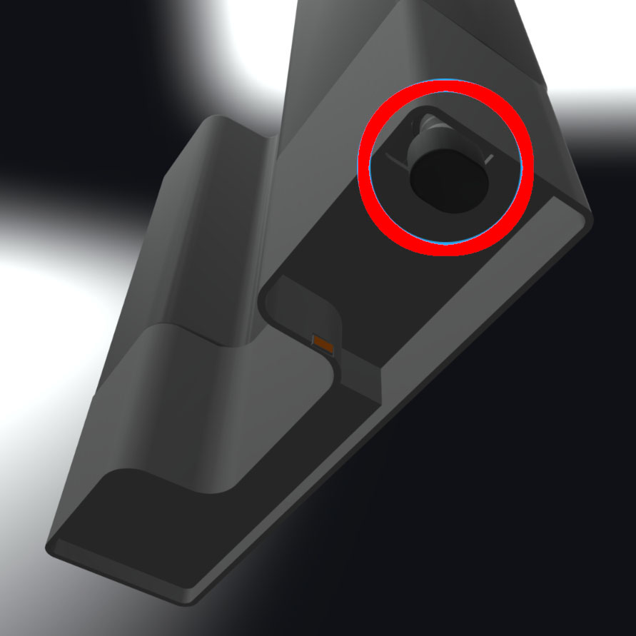
Cartridge spring fingers:
Two electrical contacts comprise the spring fingers located on the cartridge floor. The physical contact establishes an electrical connection with the cartridge ID chip to detect the cartridge.
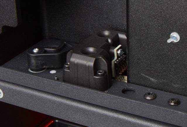
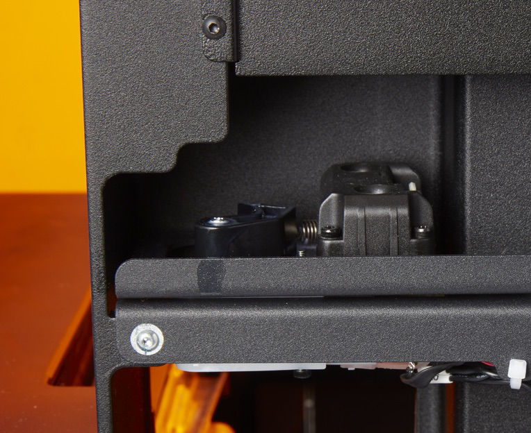
Cartridge dispense arm:
This plastic hook presses against the bite valve to dispense resin out of the cartridge into the resin tank.
Z-axis
Item/Description
Image
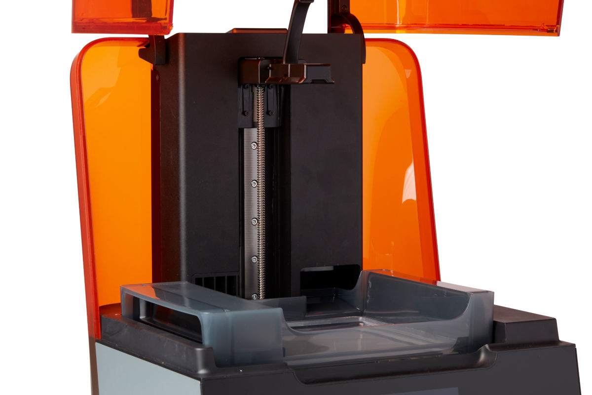
Z-tower:
This vertical tower at the back of the printer provides support for many parts of the Form 3. The build platform is raised and lowered along the Z-axis, inside the tower. The Z-tower also encloses the resin cartridge, the heater, and the mechanisms for dispensing the resin into the tank.
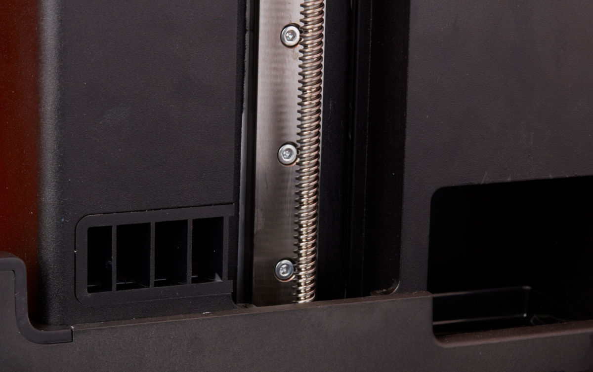
Z-axis lead screw:
The Z-axis lead screw is a threaded rod that controls the vertical motion of the build platform carriage.
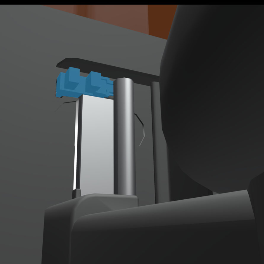
Limit switch board:
A single board connects to two optical sensors to detect when the build platform carriage reaches the top of the tower and when the build platform is installed.
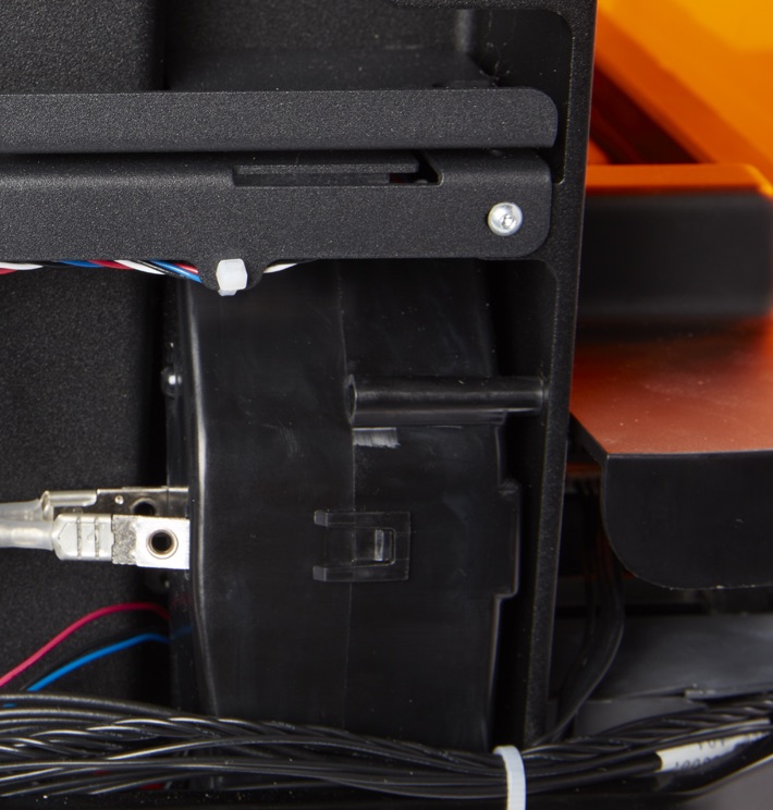
Heater:
The resin in the resin tank is heated by hot air blown out of the tower behind the resin tank. The warm air in the print chamber heats the resin, and the air temperature is sensed by a thermal sensor at the air intake.
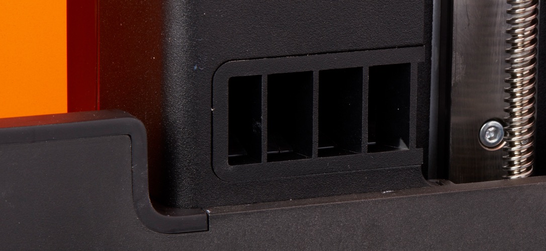
Fans:
A heating fan blows air across the heater into the resin tank.
Build platform
Item/Description
Image
Build platform:
The aluminum base provides a surface for prints to attach to. Over time, the build platform will develop scratches from part removal, which can assist with print adherence.
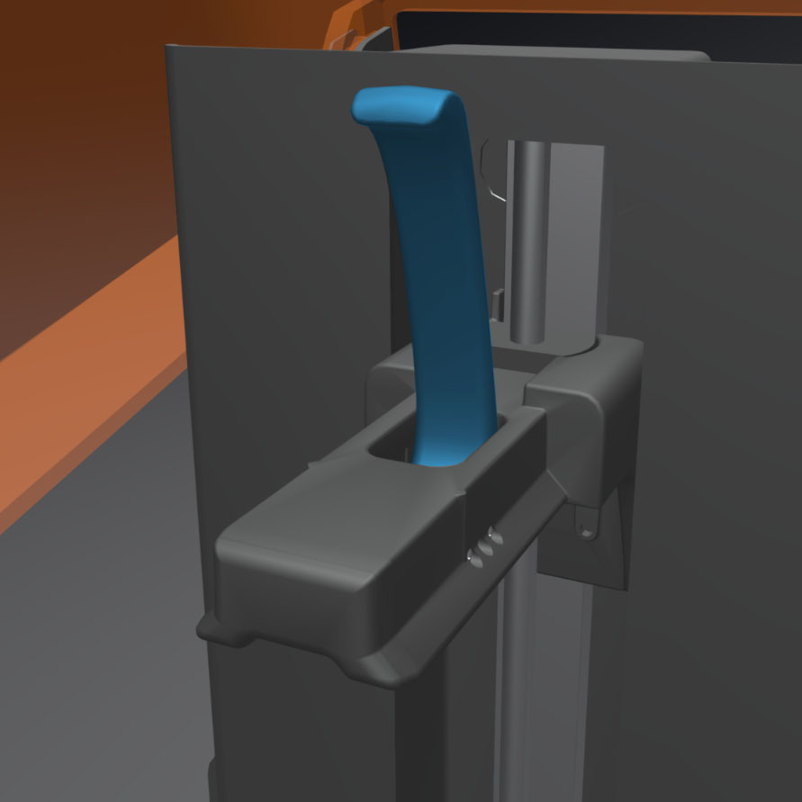
Platform lock:
This lever is part of the locking mechanism that secures the build platform.
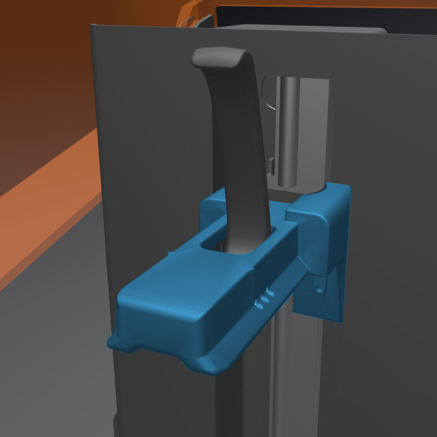
Build platform carriage:
The carriage is the metal arm that the build platform slides onto.
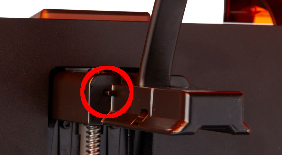
Platform lock spring:
The spring mechanism inside the build platform carriage allows the platform lock to move up and down. It also mechanically locks and unlocks the build platform.
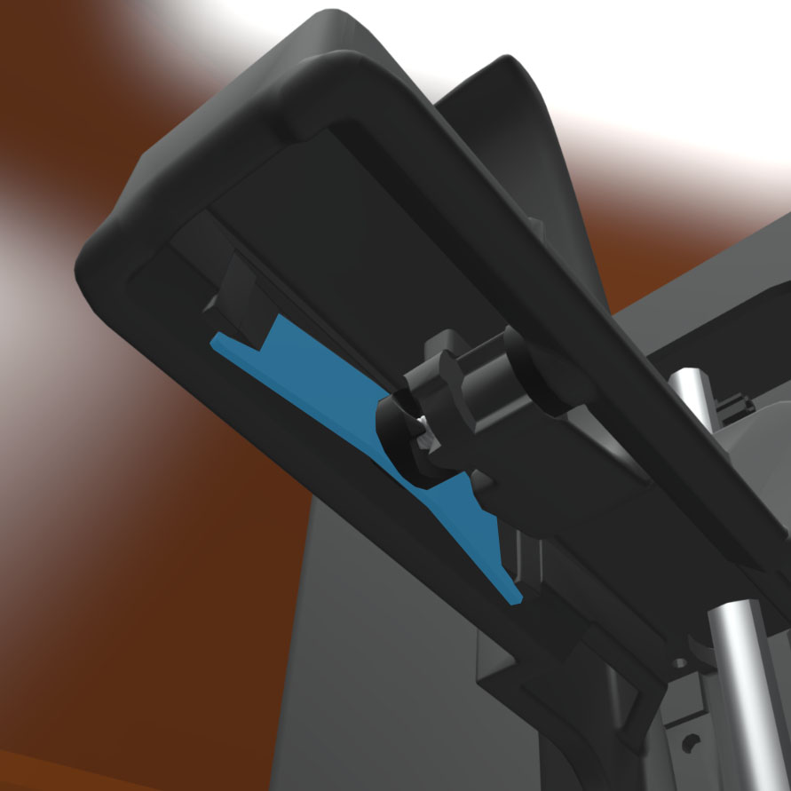
Platform lock set screws:
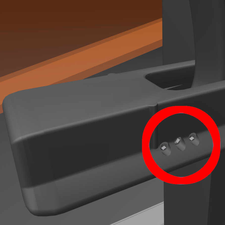
These three screws are used for adjusting the tension in the platform lock. Contact Formlabs Support before adjusting these screws, as improper adjustment can lead to damage to the machine.
Resin tank
Item/Description
Image
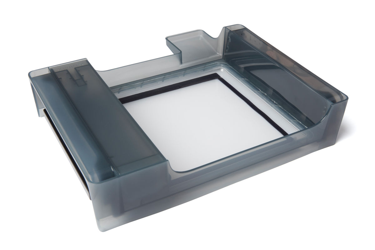
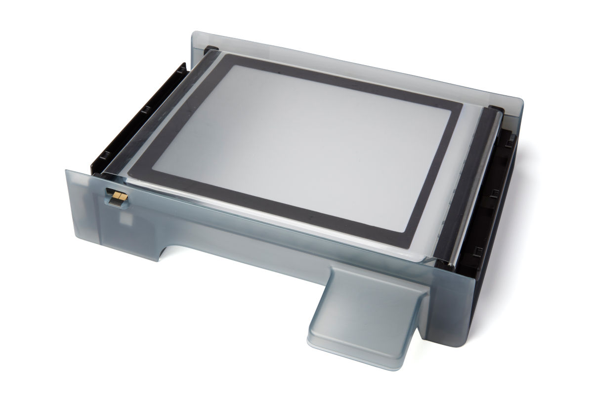
Resin tank:
The resin tank is the primary container for holding resin after it is dispensed from the cartridge. Resin is cured onto the build platform when the laser passes through the tank’s bottom film. Only use approved materials and processes to clean the resin tank and film.
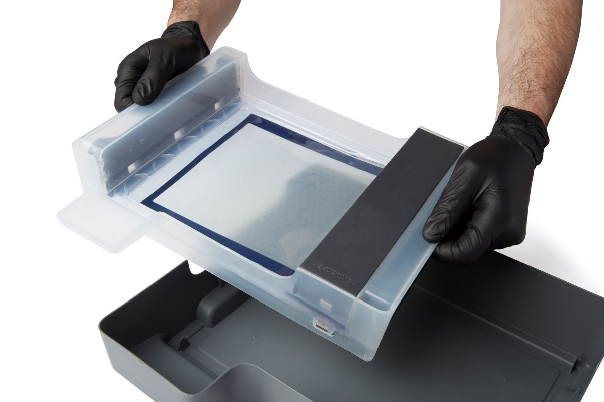
Tank handles:
Plastic handles on each side of the resin tank allow for easy insertion, removal, and carrying of the tank. Avoid touching the bottom of the resin tank, as fingerprints can leave smudges that obstruct the optical path.
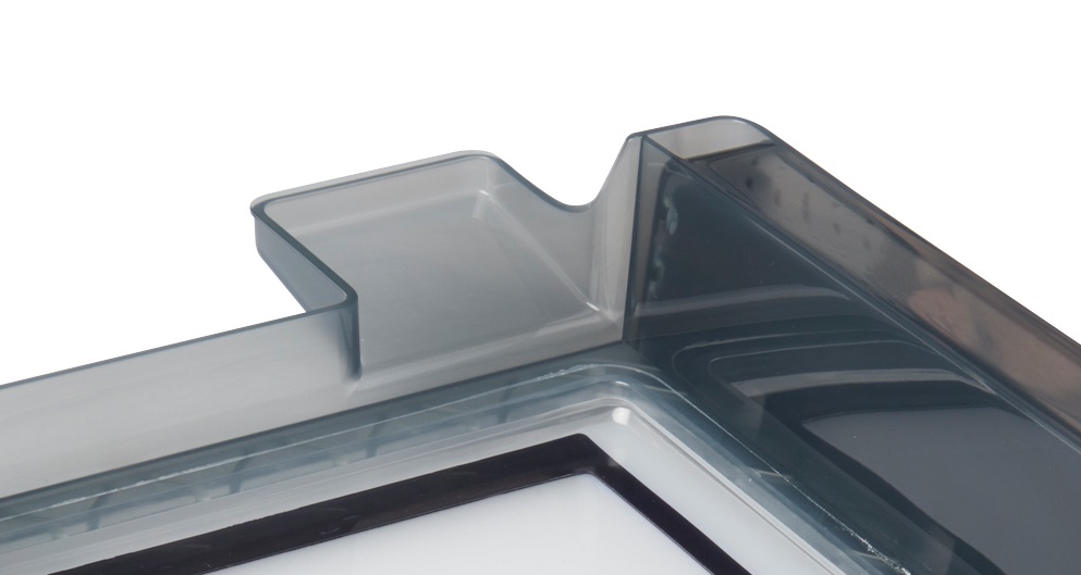
Tank spout:
This spout at the back of the resin tank sits underneath the cartridge dispense hole and receives resin from the cartridge.
Film:
A durable, dual-layer film comprises the bottom surface of the resin tank. Parts print in the resin-filled gap between the film and the build platform. The quality of printed parts depends on the film being clean and clear of damage and debris.
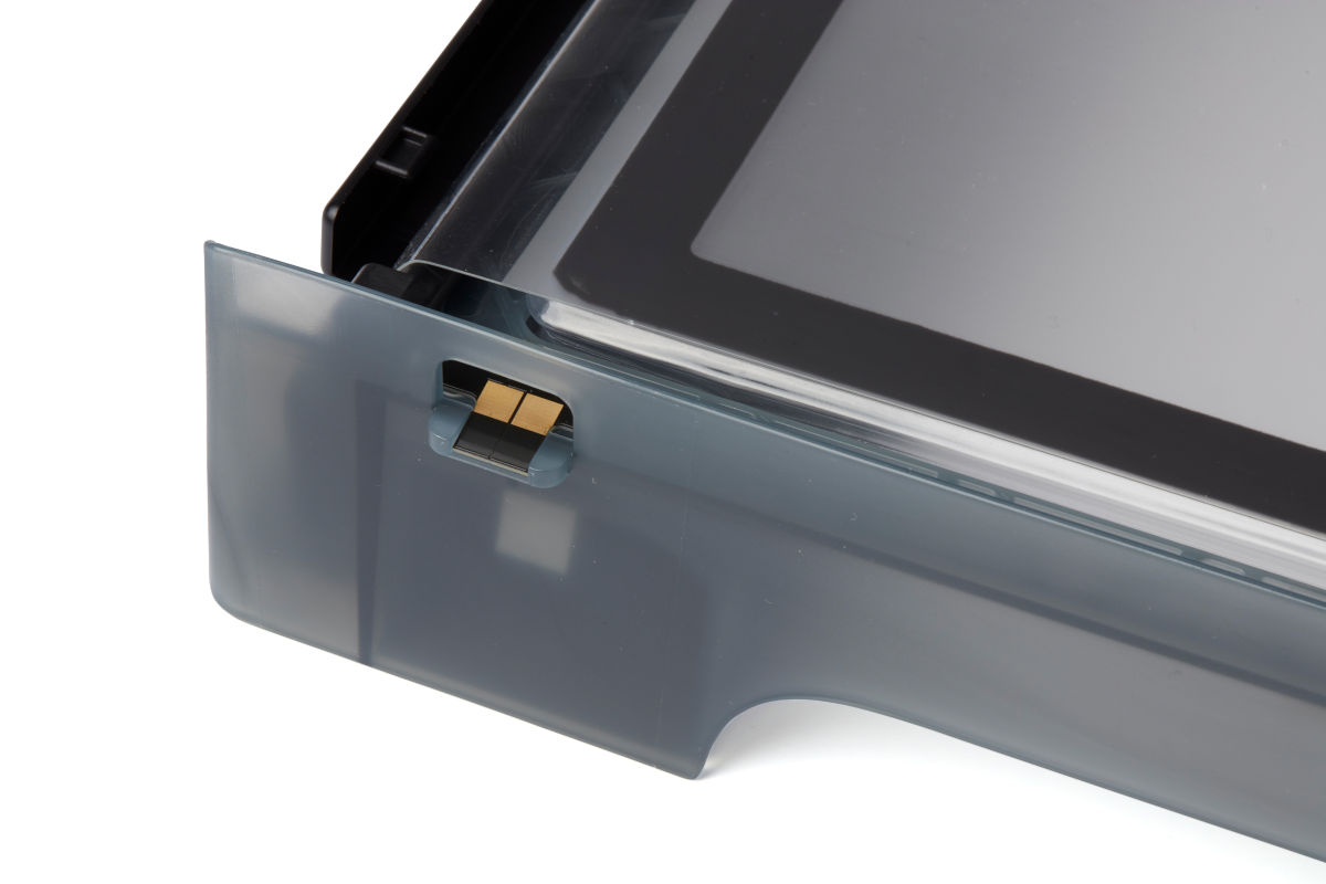
Resin tank ID chip:
The resin tank's ID chip uses Electrically Erasable Programmable Read-Only Memory (EEPROM). The tank spring fingers read the chip to detect the unique tank ID and current resin type.
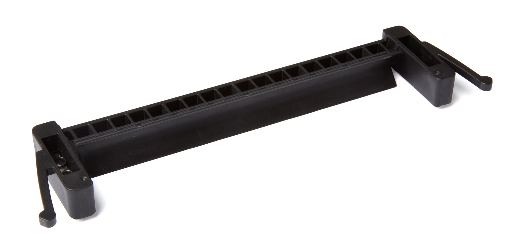
Mixer:
Each resin tank includes a mixer that improves print consistency by clearing the build area and circulating the resin. The mixer attached to the roller holder with magnetic coupling and rests under the mixer case when not in use. Scrapers on the top and bottom of the mixer clear the build platform and film, respectively.
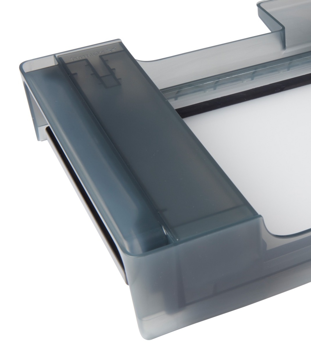
Mixer case:
When not in use, the mixer rests in a partially enclosed compartment on the left side of the resin tank. The float is permanently attached inside the mixer case.
Float:
A hinged bobber rests on the surface of the resin. The aluminum counterweight passes in front of the LevelSense board to determine the amount of resin in the tank.
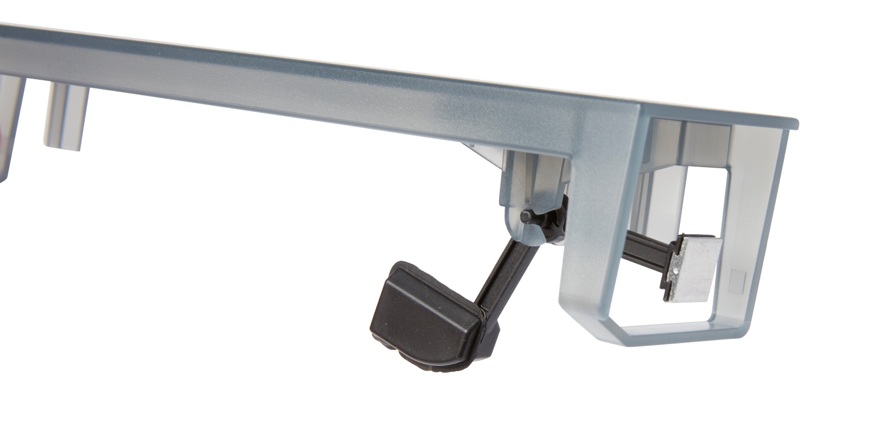
Tank case:
Each resin tank includes a lidded container for storing the resin tank when not in use.
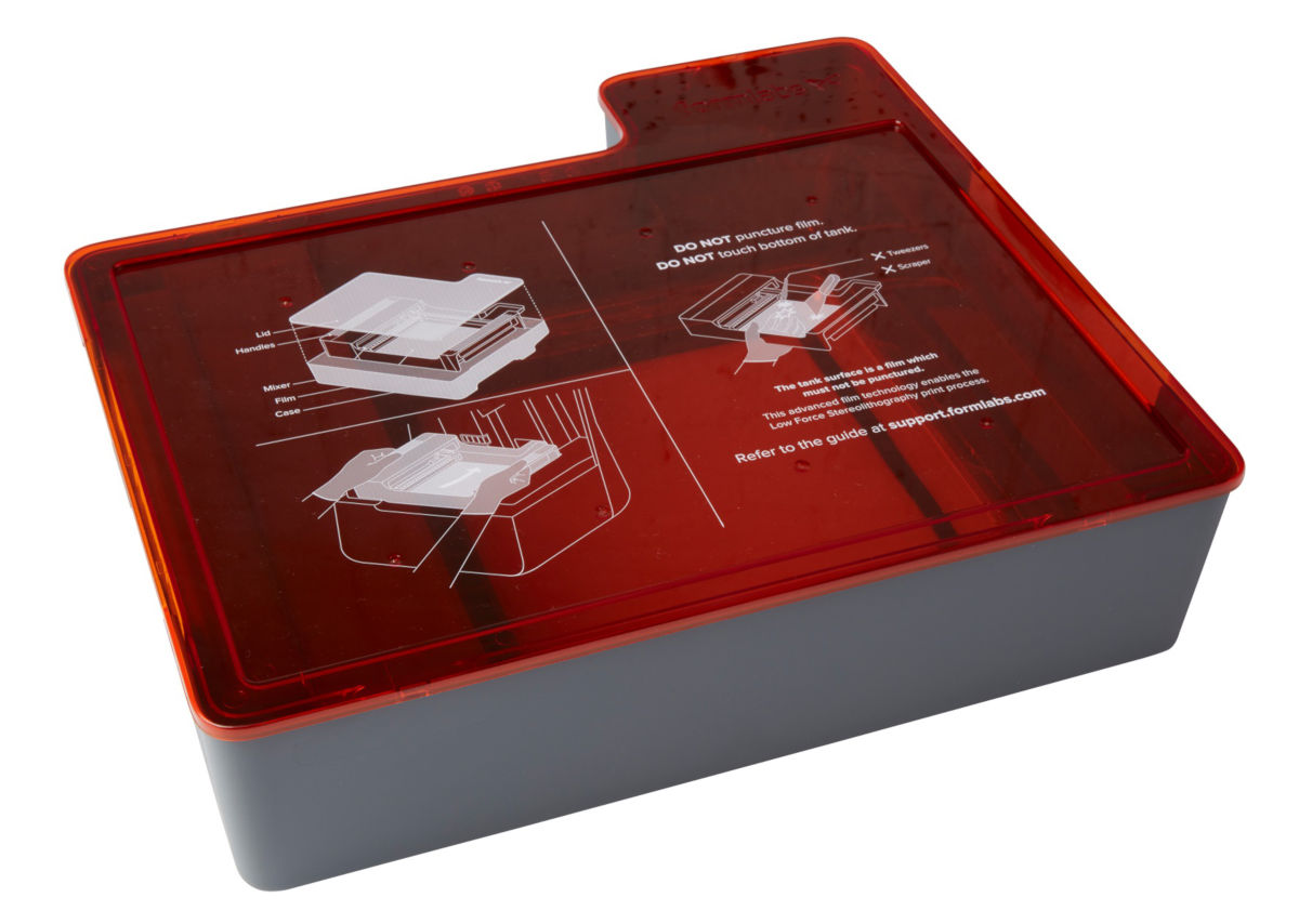
Tank tool:
Inspecting and cleaning the interior of the resin tank requires a special two-part spatula. This is the only tool to clean the interior film surface.
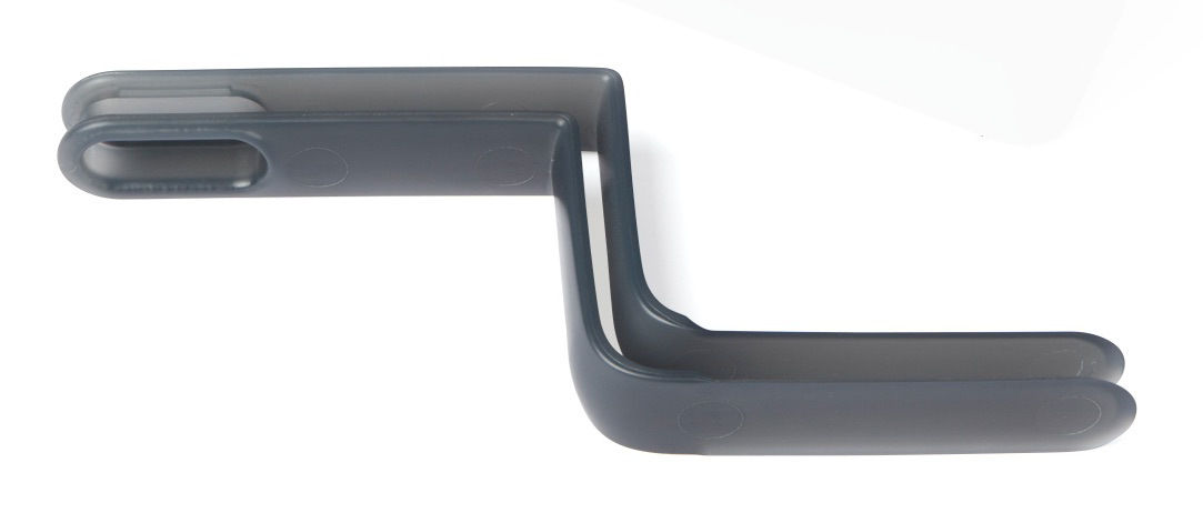
Tank carrier
Item/Description
Image
Tank carrier:
This assembly holds the resin tank and tensions the film. The tank carrier is covered by the top shell and houses the film tensioner, LevelSense, resin tank spring fingers, tank catch flexures, and interlock sensors.
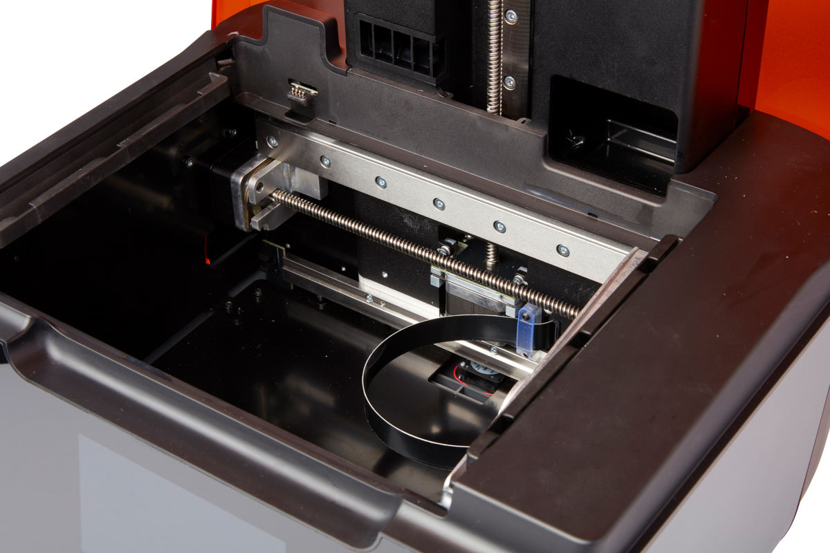
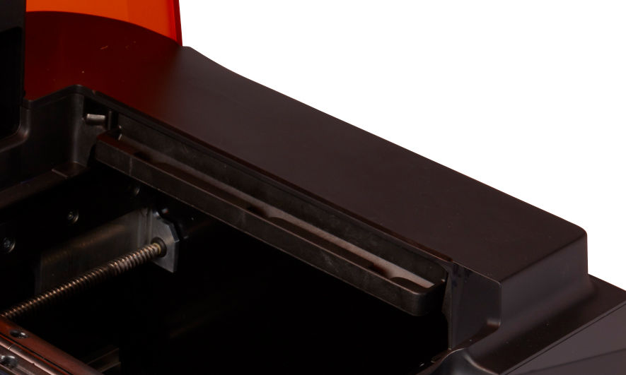
Tank carrier rails:
The resin tank side walls connect to linear slots on each side of the tank carrier. While printing, the rails pull the tank walls and the film into tension.
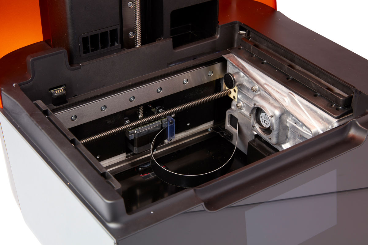
Film tensioner:
A motor pulls outward on the tank side walls to create a taut film surface in the resin tank.
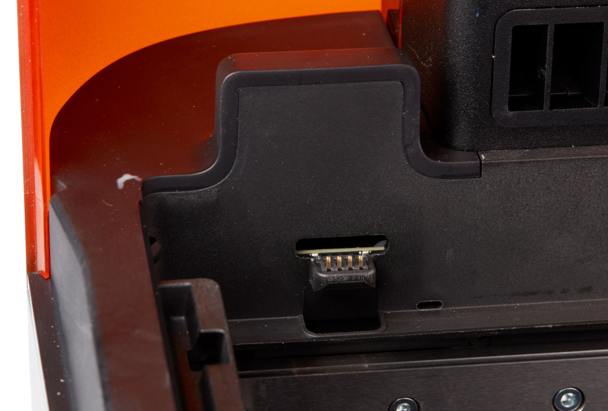
Tank spring fingers:
These electrical contacts, at the back of the resin tank carrier, read the resin tank’s EEPROM ID chip to sense the tank’s presence and to communicate the resin type to PreForm.
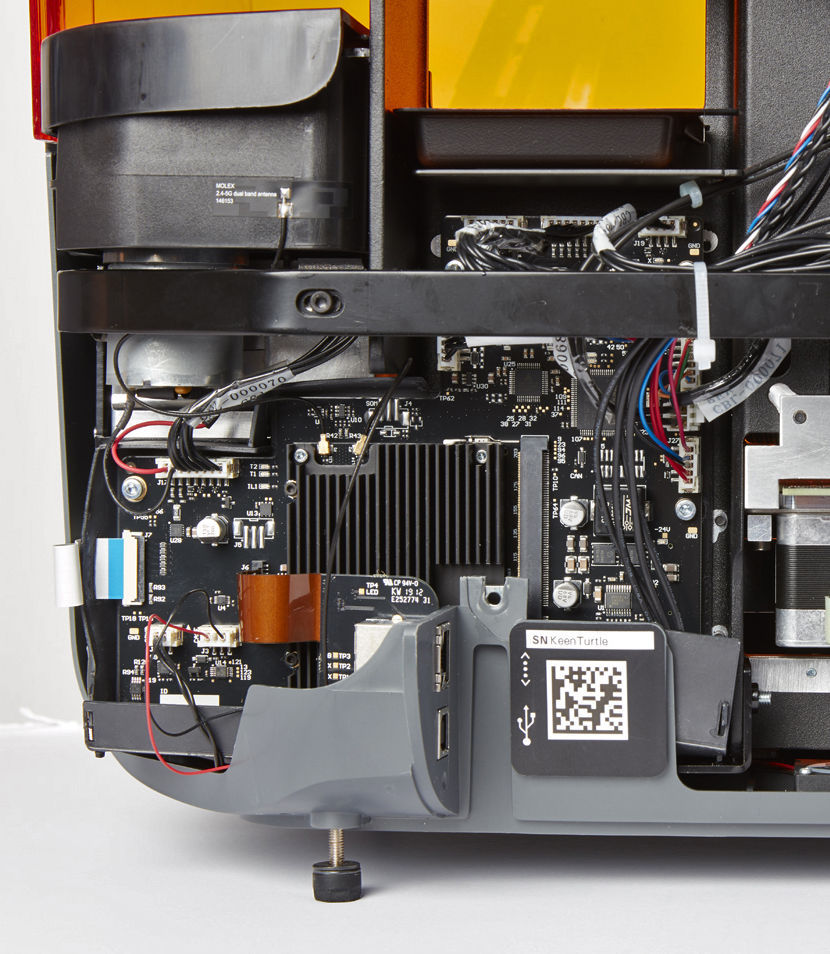
Motherboard
Item/Description
Image
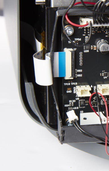
Motherboard:
The motherboard is the main circuitry through which all systems in the printer communicate.
Power supply:
The Form 3 utilizes a 100–240 V power supply. The internal power supply converts line power to +24V DC.
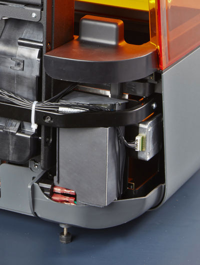
Front display connector:
This connector links the display to the motherboard via a ribbon cable.
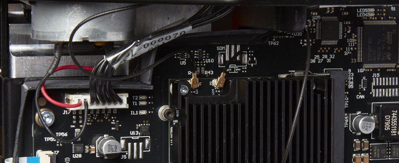
Wi-Fi antenna:
The Wi-Fi antenna enables the Form 3's wireless connectivity. The antenna is connected to the printer's motherboard.
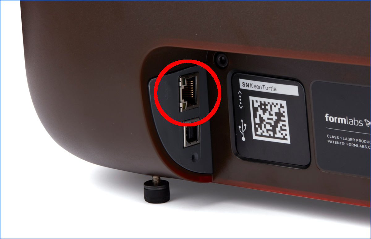
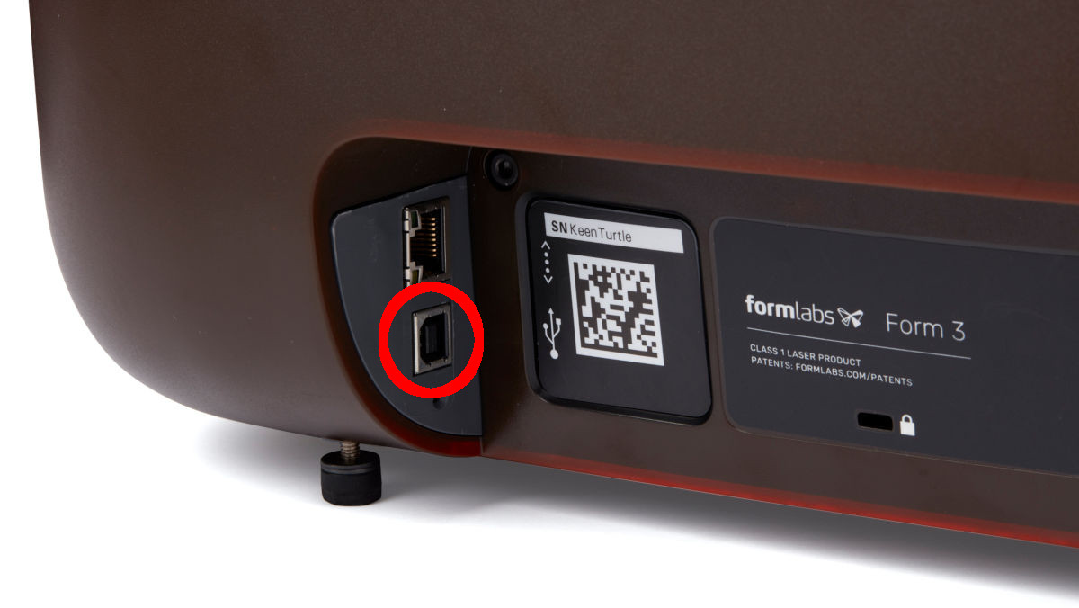
Ethernet port:
The Form 3 can connect to a network via Ethernet. The port is connected to the motherboard and can be accessed from the back of the machine.
USB port:
The Form 3 can connect to a computer via USB. The port is connected to the motherboard and can be accessed from the back of the machine.
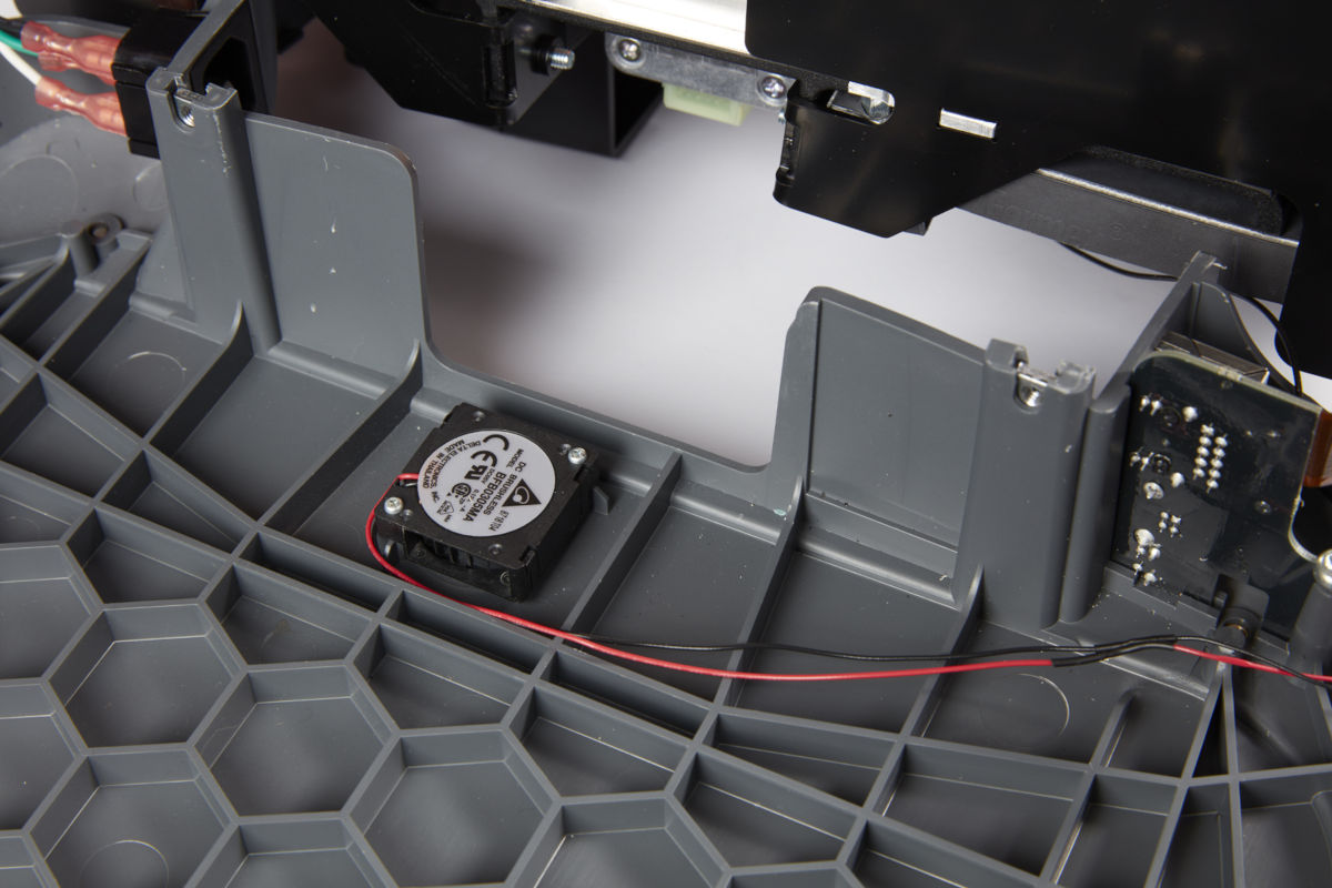
Fans:
Cooling fans pull warm air away from electronic components.
LevelSense
Item/Description
Image
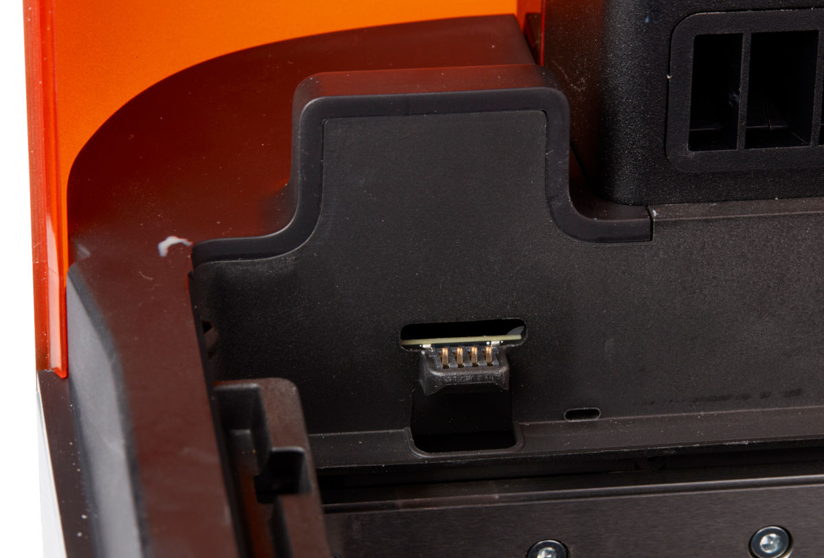
LevelSense board:
Two inductive coils determine the amount of resin in the tank by detecting the relative height of the float.
Optics
Item/Description
Image
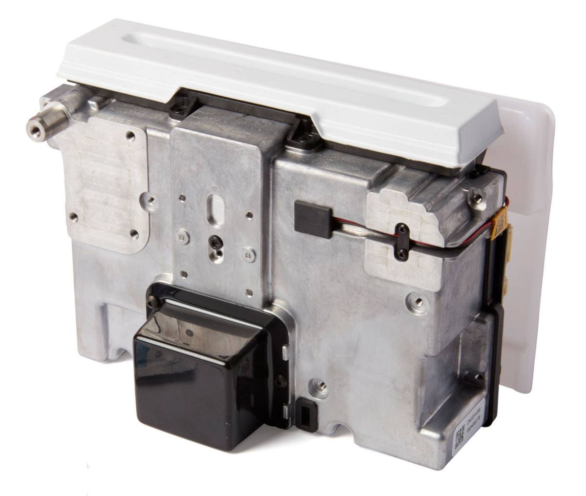
Light Processing Unit (LPU):
This interchangeable assembly contains the laser and the mirrors the control the path of the laser, ensuring a clean, crisp laser spot. The LPU is secured in the right-hand side of the LPU housing.
Laser:
The laser is the source of curing energy in the Form 3. It has a 405 nm violet diode and a maximum output of 250 mW. The Form 3 is a Class 1 laser product.
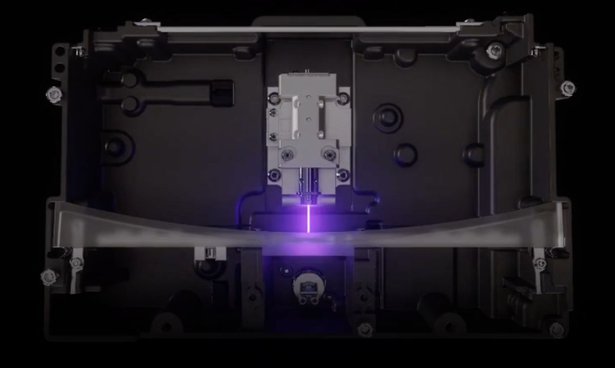
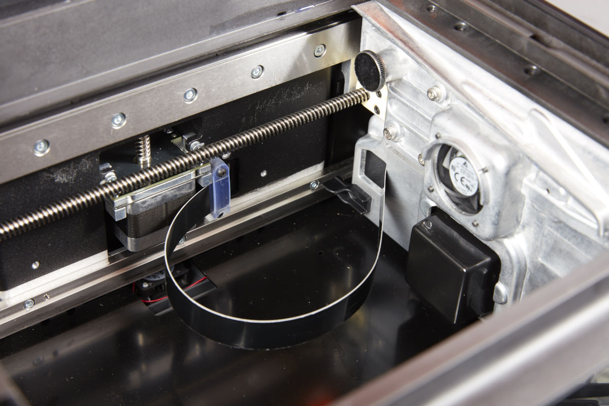
Light Processing Unit (LPU) cable:
A flat, flexible cable connects the LPU to the motherboard.
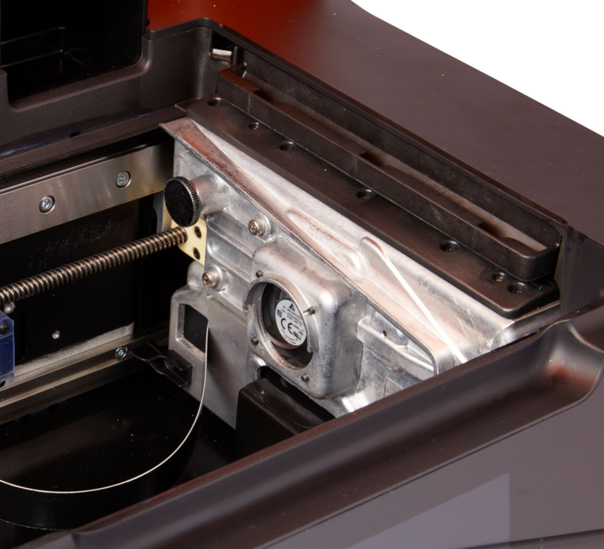
Light Processing Unit (LPU) housing:
The aluminum housing for the optics engine moves left and right, traveling along the X-axis lead screw. The LPU, roller holder, and mixer are all controlled within the LPU housing.
Roller holder:
Segmented metal rods (rollers) act as a sliding surface for smooth movement of the LPU housing across the film in the resin tank. The rollers surround the optical window. Clean rollers protect the film and preserve print quality.
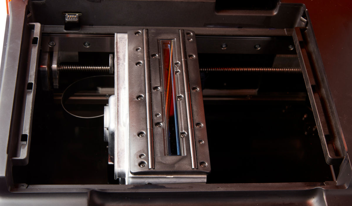
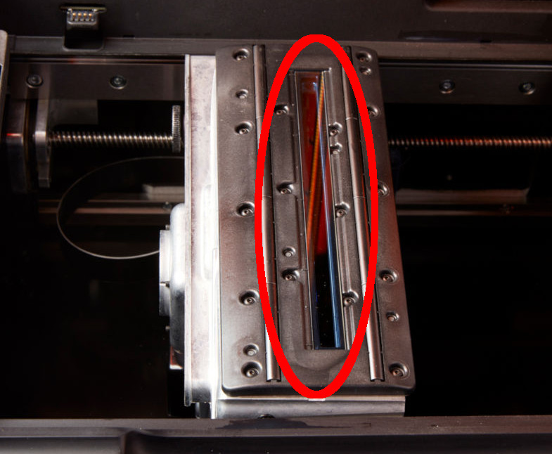
Optical window:
Located in the roller holder, the optical window is a glass plate with an anti-reflective coating. It protects the sensitive mirrors inside the LPU from dust and other contamination. Maintain a clean optical window to prevent print failures.
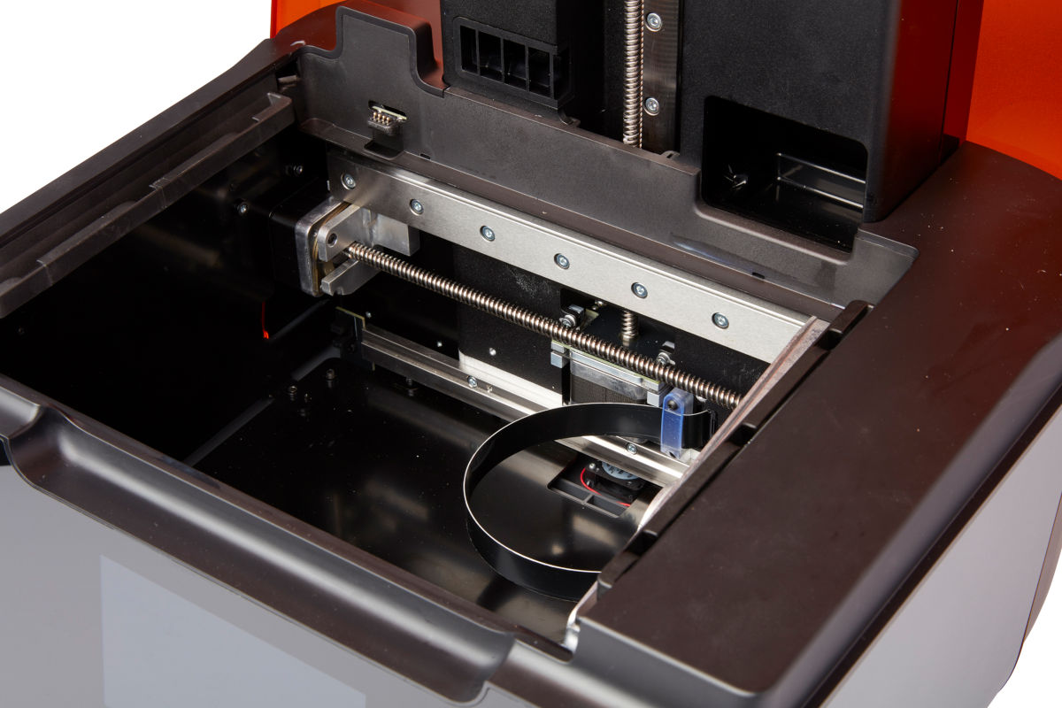
X-axis lead screw:
The X-axis lead screw is a threaded rod that controls the horizontal motion of the LPU housing.
Published date:26-Aug-2019.


