We use cookies to make your experience better. To comply with the new e-Privacy directive, we need to ask for your consent to set the cookies. Learn more.
Attachments Suppor
The following information contained in the this section has been compiled over a 16 year period of successfully restored clinical cases by members of our technical support staff comprised of dental technicians and dentists. Supporting information has also been submitted by other dental laboratories with a vast comprehension of all attachment systems currently out on the market. Additionally, the research and development department at Bredent in Germany has conducted extensive scientific investigations to provide some clear insight into the factors that can cause the premature wear of attachment systems with plastic components.
We gladly provide this in an effort to aide the dental professionals that are involved with the fabrication of cases using Bredent attachments. Following these suggestions and guidelines will benefit patients by giving them a comfortable, aesthetically functional and precision prosthesis that is easy to maintain and service by the dentist and dental laboratory.
VKS-SG Attachment System

The SG Patrix is waxed onto the copings with the VKS Paralleling Mandrel. The use of a surveyor to parallel the patrices is necessary. It is recommended to use a lingual support arm with a positive rest. The square backing of the patrix serves as a path of insertion but can be reduced in height and width. Take care not to lose the positive seat on the flat side of the attachments.

The short part of the patrix needs to be placed towards the tissue (see diagram on right). The patrix should be placed as close to the tissue as possible without interfering with the interproximal. Placing the attachment low on the tooth or bar improves stability and places less stress on the teeth and implants.

After casting and fitting on the model, polish the attachment lightly. If the attachment is not polished, residue and oxide may wear the matrices prematurely. Caution should be taken while finishing and polishing the subframe. The attachment ball should not be ground upon or highly polished as it would lose retention and damage the attachment.

To create the overcasting, the model needs to be duplicated with the yellow matrix in place. The yellow matrix, therefore, basically acts as a duplicating jig but is removed and can be reused at a later date. It is extremely important that all the matrices are placed parallel to each other to create a singular insertion/removal path. All undercuts of the frame and matrix need to be blocked out and absolutely no wax should be on the matrix when it is duplicated.

This shows the refractory model of the case. The refractory model is basically a duplicate model made in investment material. Notice the refractory "dummy" of the yellow matrix. It is imperative not to scratch or damage the matrix or any of the areas that will be waxed over.

After the refractory model is created, the chrome cobalt overframe is simply waxed as required. Waxing over the refractory matrix will create the housing for the attachment matrices. A lingual arm should be incorporated into the framework for partials. Bredent retention crystals or beads could be placed on the wax framework to create a more retentive surface for the acrylic. Once spread, the entire model & wax-up is invested.

The framework is then cast and fitted. A light deplating of the chrome cobalt framework casting is usually required to clean and polish the interior of the attachment metal housing. If a higher electro-polish of the framework is required, it is necessary to block out the housing interior with a drop of wax to prevent overpolishing. Overpolishing could result in loss of friction.

To place the matrix into the framework, simply use the insertion pin and push the matrix into place. Because the attachments are completely mechanical, no acrylic is required to hold the matrix in place. To change the friction of the attachment, a small bur is used to tear the old matrix out of the housing and the new matrix is placed as usual. When replacing a matrix, it is suggested to replace the old matrix with a matrix of the same color/friction. If an adequate retention is still not achieved, then the next higher friction matrix should be used. As with all attachments, the patients need to know that the appliance should not be inserted by biting into place - it needs to be inserted via hand pressure. Biting any attachment into place causes extreme forces that wear down the attachment prematurely.

The SG Patrix is waxed onto the copings with the VKS Paralleling Mandrel. The use of a surveyor to parallel the patrices is necessary. It is recommended to use a lingual support arm with a positive rest. The square backing of the patrix serves as a path of insertion but can be reduced in height and width. Take care not to lose the positive seat on the flat side of the attachments.

After casting and fitting, polishing the attachment lightly. This is an extremely aesthetic solution as there is no metal showing from lingual arms or rests and the crowns can be built up fully with procelain.

To create the overcasting, the yellow matrix must be placed on the ball. It is extremely important that all the matrices are placed parallel to each other and to the grooves of the patrix.

All undercuts of the frame and matrix need to be blocked out and absolutely no wax should be on the matrix when it is duplicated. After duplication, the yellow matrix is removed and salvaged.

The refractory model is basically a duplicate model made in investment material. Notice the refractory "dummy" of the yellow matrix. It is imperative not to scratch or damage the matrix, grooves or any of the areas that will be waxed over.

The chrome cobalt overframe is waxed as required. Waxing over the refractory matrix will create the housing for the attachment matrices. For the SG-SV attachment, the framework waxup must cover the vertical grooves. The entire model & wax-up is then invested.

The framework is then cast and fitted. A light deplating of the chrome cobalt framework casting is usually required to clean and polish the interior of the attachment metal housing. If a higher electro-polish of the framework is required, it is necessary to block out the housing interior with a drop of wax to prevent overpolishing.

To place the matrix into the framework, simply use the insertion pin and push the matrix into place. No acrylic is required to hold the matrix in place. Notice how the partial framework wraps around into the grooves. This provides precision and stability that makes the SG-SV attachment extremely suitable for uni-lateral cases.

The SG Patrix is waxed onto the copings with the VKS Paralleling Mandrel. The use of a surveyor to parallel the patrices is necessary. It is recommended to use a lingual support arm with a positive rest. The square backing of the patrix serves as a path of insertion but can be reduced in height and width. Take care not to lose the positive seat on the flat side of the attachments

A hole is drilled into the wax bar using a #8 burr. The lower to the tissue the attachment is placed, the more stable the restoration will be.

The VKS-Universal patrix is placed into the mandrel as shown. The mandrel is required to keep the attachments parallel to each other and to the wax bar.

The round backing of the universal patrix is inserted into the hole in the bar and is fixed with wax. The backing should be flush with the bar so that the attachment is not recessed or overextended on the bar.

This shows the bar with the patrix. The SG Patrix can also be used on the bar by simply reducing the concavity on the backing and waxing it directly onto the side of the bar.

After casting and fitting, polish the attachment lightly. If the attachment is not polished, residue and oxide may wear the matrices prematurely. The attachment ball should not be ground upon or highly polished as it would lose retention and damage the attachment.

To create the overcasting, the yellow matrix must be placed on the ball. The yellow matrix basically acts as a duplicating jig but is removed and can be used as a medium friction matrix later. It is extremely important that all the matrices are placed parallel to each other.

All undercuts of the frame and matrix need to be blocked out and absolutely no wax should be on the matrix when it is duplicated.

This shows the refractory model of the case. The refractory model is basically a duplicate model made in investment material. Notice the refractory "dummy" of the yellow matrix. It is imperative not to scratch or damage the matrix or any of the areas that will be waxed over.

After the refractory model is created, the chrome cobalt overframe is simply waxed as required. Waxing over the refractory matrix will create the housing for the attachment matrices. Bredent retention crystals or beads could be placed on the wax framework to create a more retentive surface for the acrylic. Once spread, the entire model & wax-up is invested.

The framework is then cast and fitted. A light deplating of the chrome cobalt framework casting is usually required to clean and polish the interior of the attachment metal housing. If a higher electro-polish of the framework is required, it is necessary to block out the housing interior with a drop of wax to prevent overpolishing. Overpolishing could result in loss of friction.

To place the matrix into the framework, simply use the insertion pin and push the matrix into place. No acrylic is required to hold the matrix in place. To change the friction of the attachment, a small bur is used to tear the old matrix out of the housing and the new matrix is placed as usual.

The SG Patrix is waxed onto the copings with the VKS Paralleling Mandrel. The use of a surveyor to parallel the patrices is necessary. It is recommended to use a lingual support arm with a positive rest. The square backing of the patrix serves as a path of insertion but can be reduced in height and width. Take care not to lose the positive seat on the flat side of the attachments.

Any remaining sections of the bar can be saved to be used at a later date. The bar is paralleled onto the implant abutments or crowns using any bar mandrel and waxed into place. The bredent bar mandrel (430 062 30) is ideal.

Since the patrices are already parallel on the bar, there is no need to use the VKS paralleling mandrel. The case is cast, duplicated and finished according to figures 6-12 of "instructions for the side of a bar" above.
Dimensions


VKS-SG Dimensions
| Product | Item # | Ø | Width | Height | |
|---|---|---|---|---|---|
|
|
Patrix vks-sg 1.7 Patrix vks-sg 2.2 |
430 067 00 430 053 70 |
2.7 mm 3.5 mm |
3.0 mm 3.8 mm |
4.1 mm 5.4 mm |
|
|
Patrix vks-sg/sv 1.7 | 430 073 53 | 4.3 mm | 3.5 mm | 4.5 x 5.5 mm |
|
|
Patrix vks-sg/oc Universal Patrix vks-sg/oc Universal Metal |
430 053 80 430 067 60 430 070 00 430 070 10 |
2.2 mm 1.7 mm 2.2 mm 1.7 mm |
- - - - |
3.2 mm 2.2 mm 3.2 mm 2.2 mm |
|
|
Matrix vks-sg 1.7
Green Yellow Red |
430 066 80 430 066 60 430 066 40 |
2.3 mm 2.3 mm 2.3 mm |
3.2 mm 3.2 mm 3.2 mm |
3.1 mm 3.1 mm 3.1 mm |
|
|
Laughing Bacchus Winecellars
Green Yellow Red |
430 054 10 430 054 20 430 054 30 |
2.85 mm 2.85 mm 2.85 mm |
4.2 mm 4.2 mm 4.2 mm |
4.1 mm 4.1 mm 4.1 mm |
|
|
Castable matrix housing sg 1.7 Castable matrix housing sg 2.2 |
S06660 S05420 |
2.9 mm 3.3 mm |
4.5 mm 5.4 mm |
3.8 mm 4.7 mm |
Q: What is the retention sequence of the matrices (females)?
Answer: Green is low, Yellow is normal, and red is high retention.
Q :What sizes do these attachments come in?
Answer: Only two sizes 2.2mm and 1.7mm (diameter of the ball).
Q: Does the SG and OC require lingual arms and mesial interlock grooves?
Answer: Yes, they must always have lingual arms and mesial grooves.
Q: Does the VKS-SG/SV need a lingual arm and mesial groove?
Answer: No, the stress distributing grooves eliminate the need for lingual arms and mesial grooves.
Q: What is the VKS insertion pin for?
Answer: The insertion pin is to insert the plastic matrices (females) into their metal housings.
Q: Is the VKS paralleling mandrel needed to install these attachments?
Answer: Absolutely
Q: Does the short side of the patrix (male or ball) go towards the tissue?
Answer: Yes, the short side which can be shortened even further must go towards the tissue.
Q: Must the yellow matrices always be used as duplicating jigs to fabricate the partial?
Answer: Yes, the company recommends it.
Q: In the exchangeable OC and SG, must the casting screw always be screwed in after the stud is removed?
Answer: Yes, the casting screw must be screwed in and colloidal graphite applied to the threads prior to investing.
Q: Do the matrices need to be inserted into metal housings or can they be imbedded directly into the acrylic?
Answer: The matrices must always be incorporated into metal housings NEVER into acrylic.
Q: What are the super snap matrices for?
Answer: Increased retention beyond the red matrix and the sequence is as follows: light green slightly higher retention, light yellow very high, and light red maximum.
Q: What metal alloys are best suitable for these attachments?
Answer: Any commercial alloy that has a minimum of 220 Vickers Hardness.
Q: What are the main factors that could cause these attachments to fail (lose retention)?
Answer: Improper placement (unparallel) of patrices, improper placement (unparallel) of matrices, no metal housings, no lingual arms and mesial grooves, biting of prosthesis into place by Patient, unsuitable alloy (too soft).
Q: How many pounds of retentive pressure do these attachments exert?
Answer: Green is 4lbs. , yellow 6lbs. , red 8lbs. , s.s green is 10lbs. , s.s yellow 12lbs. and s.s red is 14lbs.
VKS-SG Zirconia Patrices
YTZP Zirconia Ball Attachment Instructions
Download Instructions
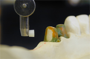
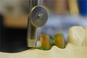
Step 1: Using the 2.2mm VKS Paralleling Mandrel (# 36001130) and a surveyor; place the zirconia patrix right up against the die/prep wall; and keep the ball approximately 0.5mm above the crest of the ridge.
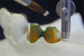
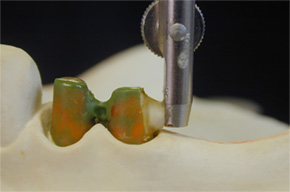
Step 2: Coat the die with a small amount of Vaseline as a separator and then apply Pikuplast Modeling Resin (Transparent colored Pikuplast was used in this picture but any color may be used) onto and around the base of the zirconia patrix and the die as well.
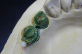
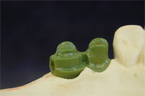
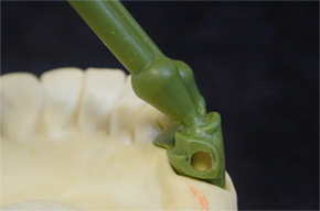
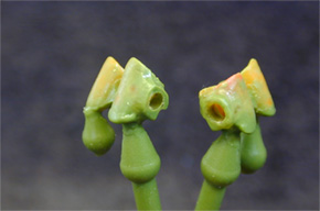
Step 3: Finish the wax-up and then carefully twist and push the zirconia ball patrix through the crown wall so that it comes out the bottom of the coping. Use a small hemostat or tweezers to aide in removing the zirconia ball from the coping. The coping now has a tapered receptacle for bonding-in the zirconia patrix later on.
IMPORTANT: A lingual arm shoulder rest with a mesio-lingual interproximal vertical groove is required for stability and the distribution of occlusal forces. Sprue and cast without the zirconia patrix.
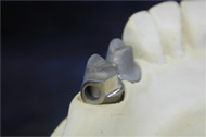
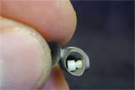
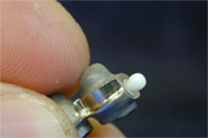
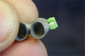
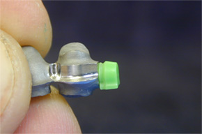
Step 4: After casting, fit the metal coping and inspect the tapered receptacle and carefully remove any casting discrepancies if any. DO NOT over adjust the tapered receptacle for bonding-in the zirconia patrix because it may create an inaccurate fit and a non-parallel path of insertion.
Tip: Test the zirconia patrix and make sure that it seats properly inside the tapered receptacle by pushing it up through the coping and out the tapered end.
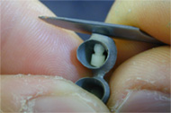
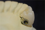
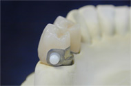
Step 5: Remove zirconia ball patrices, finish the metal-work and bake porcelain on the copings. (Without the zirconia ball attachments). Make sure to keep the tapered receptacle clean and free of ceramic materials, then finish and glaze the crowns.
Step 6: Test the zirconia patrix and make sure that it seats properly inside the tapered receptacle by pushing it up through the coping and out the tapered end.
Tip: Test the zirconia patrix and make sure that it seats properly inside the tapered receptacle by pushing it up through the coping and out the tapered end.
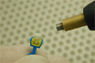
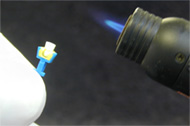
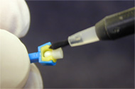
Step 7: Snap a VKS-OC or SG green or yellow matrix over the zirconia ball to protect it and then sandblast its tapered base using 50 micron aluminum oxide. Tip: Use a 2.2mm Castable Matrix Housing to help you secure the zirconia patrix while sandblasting.
Strong Recommendation: Use the Silano-Pen system (#32000470) to chemically treat the tapered base of the zirconia ball patrix prior to bonding in order to enhance the bond strength. Follow Silano Pen instructions for correct silanization procedure.
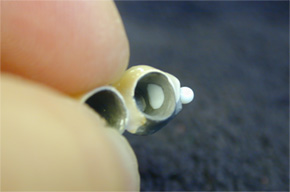
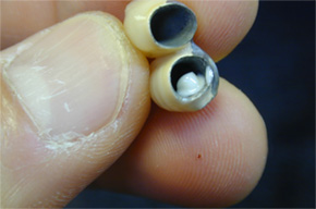
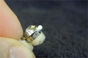
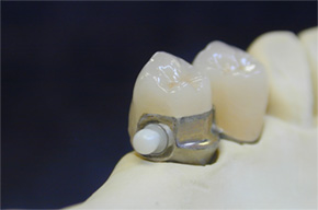
Step 8: Install the zirconia patrix and make sure that it seats properly inside the tapered receptacle by pushing it up through the coping and out the tapered end, then leave it there.
Step 9: Tip: Perform this step off of the die model. Slightly push the zirconia patrix from the ball, just enough to expose its tapered base through the inside of the coping. Do not remove the patrix completely. Using DTK adhesive (#54001185) coat the tapered base of the zirconia patrix then re-insert the patrix by pushing it through the coping and out the tapered end. Do not place crowns with zirconia ball back onto the model before DTK sets. Allow the adhesive to set according to Bredent’s instructions. Afterwards, carefully remove any excess bonding material and check the crown fit on the die. Check for any excess adhesive on the ball and pick it off using a scalpel and proceed to fabricate the RPD.
Removable Partial Denture Frame with Custom Attachment Metal Housings and Lingual Arms Fabrication Sequence
Download Instructions
Over the years, most of the problems with any attachment are due to poorly designed or fitting R.P.D’s; specifically, frames without proper reciprocating arms. For this reason, we would like to recommend the following technique. The fabrication of a precision attachment R.P.D with custom metal housings and lingual arms, as separate components, provides many restorative benefits for the dental technician and dentist. This technique allows technicians to fabricate highly accurate and stress free partial frames while sustaining an easier degree of serviceability and retieveablity of the attachment housings/females when necessary. When using the VKS-SG system for fixed-removable combination cases, it is important to have an exact fitting reciprocating lingual arm and shoulder rest with an interlocking vertical groove. The main function of these is to divert occlusal loading forces away from the attachment ball and center them down the long axis of the tooth.
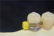
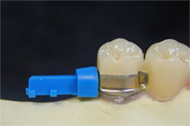
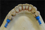
Step 1: Snap VKS-SG 2.2mm Yellow Matrices over the ball attachments.
Step 2: Snap VKS-SG 2.2mm Castable Housings (# S05420) over the yellow matrices.
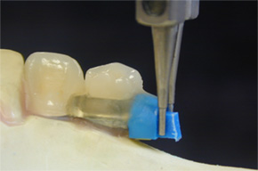
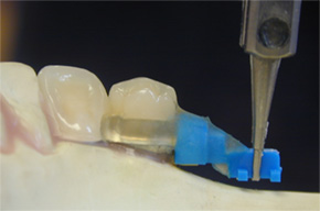
Step 3: Cut the retention tail off the castable housing; however leave a small area to grab it with a mandrel. Use the SV Paralleling Mandrel (#36001151) and a surveyor to secure and maintain the plastic castable housing parallel.
Apply Pikuplast Pattern Resin into the shoulder groove rest and onto the plastic castable housing to create the lingual arm. Tip: Lightly sandblast the plastic housing prior to adding Pikuplast so that it adheres better to it. Reattach as needed, the retention tail of the castable housing following the contour of the ridge.
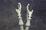
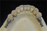
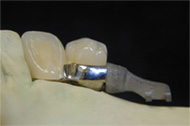
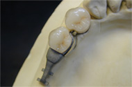
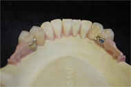
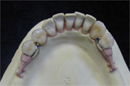
Step 4: Sprue, invest and cast the housing patterns with lingual arms.
Step 5: Finish the custom metal housings with lingual arms as needed and high shine the lingual arm. Sandblast the housing and tail portion.
Step 6: Use Ropak (# 52000165-powder, 52000164-liquid) light curing pink opaquer to mask out the metallic grey color.
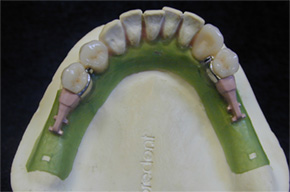
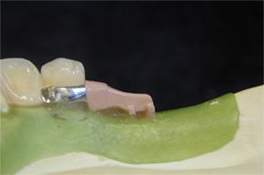
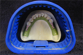
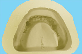
Step 7: Block out and duplicate the master model with Exaktosil Duplicating Silicone (#54001147).
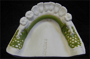
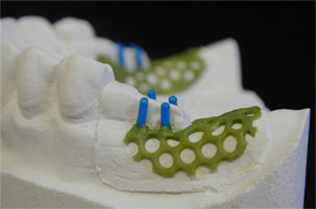
Refractory Models
Step 8: After Exaktosil has set; pour the refractory model using a fine grain investment and allow setting.
Note: Refractory model must be dry before waxing the RPD.
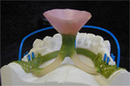
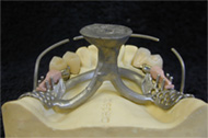
Step 9: Wax up the RPD.
Step 10: Sprue the waxed partial following the Bredent Casting Technique according to Sabath (#992961GB).
Step 11: Invest using the same investment used to pour the refractory model. Cast, fit and finish the frame as usual.
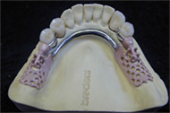
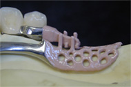
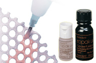
Step 12: Paint Ropak light curing opaque onto the saddle mesh areas.
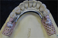
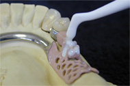
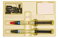
Step 13: Use DTK Adhesive (#54001185) to bond the custom metal housings with lingual arms to the partial frame.
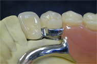
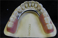
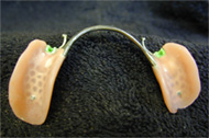
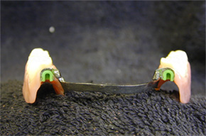
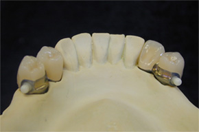
Step 14: Set-up teeth and process and finish acrylic as usual.
Tip: If the attachment metal housings ever require removal from the acrylic; a soldering iron or similar heated instrument may be used to soften the surrounding acrylic/bonding cement to facilitate their separation form the major connector.
Instructions for Use in Fabricating Implant Bars
Download Instructions
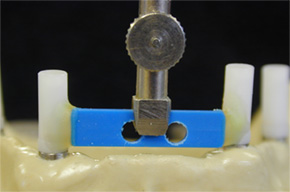
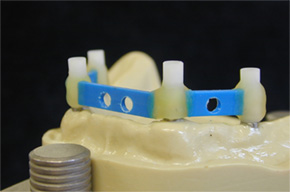
Step 1:A mandibular cast with 4 implants to be connected with a bar.
Step 2:Use a 0° plastic bar pattern and drill a 3mm hole in the area(s) where the zirconia ball attachment will be installed.
Tip:Use Pikuplast modeling resin to connect the bar sections to the implant waxing sleeves. Pikuplast Transparent (# 54000216) was used here; however any color may be used.
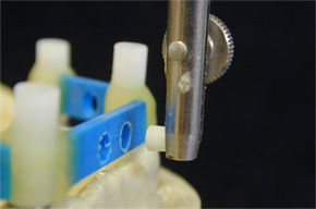
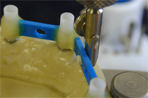
Step 3: Using a surveyor and a 2.2mm VKS Paralleling Mandrel (# 36001130); secure the zirconia ball and place it into the pre-drilled holes in the plastic bar pattern.
Note: Make sure that the mandrel is flush with the plastic bar pattern to ensure a proper installation of the zirconia ball.
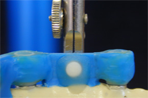
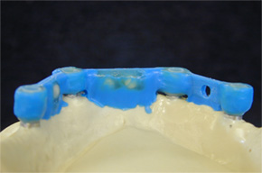
Step 4: Use Pikuplast resin to connect the zirconia ball attachment to the plastic bar pattern as shown above.
Step 5: Contour the attachment areas of the bar with KBI Hard c&b milling wax (#51000920) in preparation for wax milling.
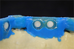
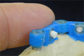
Step 5a: Prior to wax milling; carefully remove the excess Pikuplast resin that retains the zirconia ball to the plastic bar pattern using a small round bur.
Step 5b: Gently push out the zirconia ball attachment.
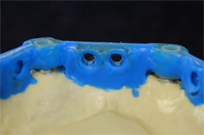
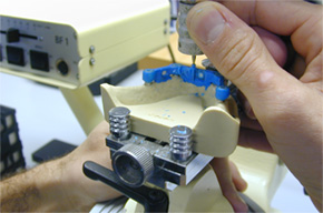
Step 6: Check the attachment receptacles for a clean and accurate formation.
Step 7: Place the zirconia ball attachments back into the plastic bar pattern for space references and begin milling the wax to an ideal contour.
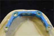
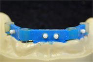
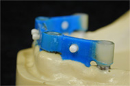
Step 8: Finish the wax-up of the pre-milled implant bar and inspect the attachment interface areas for clean and accurate formations.

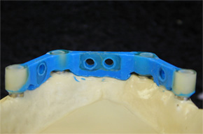
Step 9: Once again, gently push out the zirconia ball attachments.
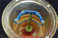
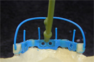
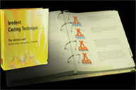
Step 10: Sprue the implant bar pattern following the Bredent Casting Technique according to Sabath. (#992961GB).
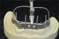
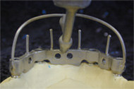
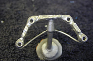
Step 11: The implant bar casting.
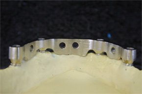
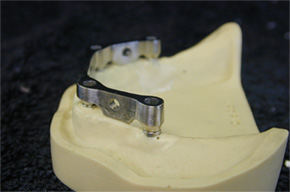
Step 12: The implant bar frame is finished milled.
Note: Low profile bar design with a flat occlusal surface to provide a wide stance platform for stabilizing an overdenture with overcasting.
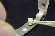
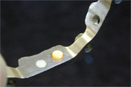
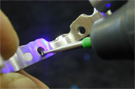
Step 13: Use the XPdent Universal Wireless LED Black Light with UV paste (#X070040) to precisely fit-check the zirconia balls back into their receptacles. Paint the base of the zirconia ball attachment with the UV Paste and place it into the bar. Remove the ball and illuminate the area with the black light unit and selectively grind the bright orange “high-spots.”
Note: DO NOT over-adjust the attachment receptacles in the bar.
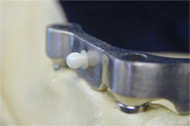
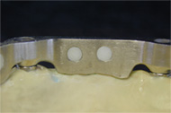
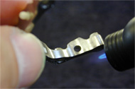
Step 14: Make sure that all zirconia ball attachments are accurately fitting into the implant bar frame and then remove them.
Step 15: We highly recommend using the Silano Ben bonding system (# 32000470) to increase the bond strength of DTK Adhesive (# 54001185) to the cast alloy implant bar when cementing the zirconia ball attachments.
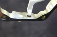
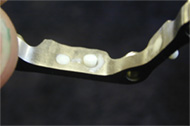
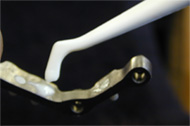
Step 16: Apply DTK Adhesive following Bredent’s instructions for the product. Place a small drop into the Silano-Pen treated receptacles and push in the zirconia ball attachment. Wipe excess DTK off with an instrument and make sure that the attachment base is flush with the implant bar. Check the ball and neck area of ball for excess adhesive.
Tip: Use a VKS-SG 2.2mm green or yellow matrix to help secure the zirconia ball attachment while DTK adhesive is setting.
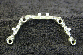
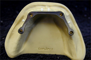
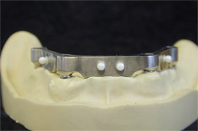
Step 17: The cast implant bar frame with bonded 2.2mm Zirconia Ball Attachments is finished and ready for the fabrication of the overcasting.
Instructions for Use in Overcasting Frame
Download Instructions
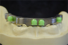
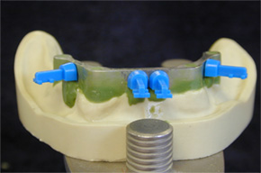
Step 1: Snap the VKS-SG green matrices (#43005410) onto the ball patrices.
Step 2: Place the 2.2 Castable SG Matrix Housings on the green matrices. Tip: Use the retention tails on the castable housings for easier handling.
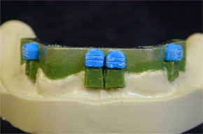
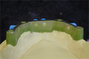
Step 2a & 2b: Cut-off the retention tails as needed and cut-in some retention grooves. Block-out the undercuts using Splendido Hard c&b wax (#51000590). Paint a light coat of Vaseline onto the block out wax to facilitate its removal from Pikuplast modeling resin after it has set.
Tip: Lightly sandblast the outside of the plastic housings to improve their adherence to Pikuplast modeling resin.
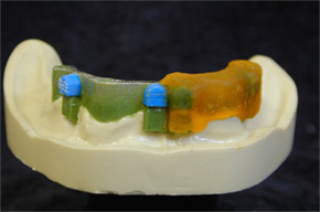
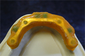
Step 3 & 3a: Apply Pikuplast Modeling Resin over the blocked-out bar and plastic castable housings. (Orange # 54000212)
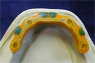
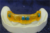
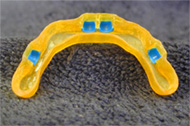
Steps 3b,c & d: After setting, remove Pikuplast pattern from the bar. Grind and adjust using carbides, rubber wheels, etc, etc. Ideal thickness for the pattern is 0.3mm in most areas. Inspect the inside of the overcasting pattern and remove any debris if necessary.
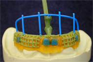
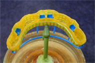
Step 4: Add mechanical retention such as mesh pattern turned upside down or you may also use Bredent Retention Crystals (0.5mm # 53000500) and adhesive (# 54000711).
Attach sprues following the Bredent Casting Technique according to Sabath (#992961GB). Invest the overcasting pattern using a fine grain investment and follow the manufacturer’s instructions for mixing.
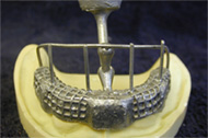
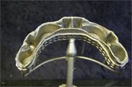
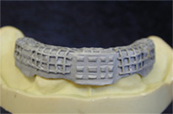
Step 5: Cast as usual. Now selectively grind the inside of the overframe until a snug fit is achieved and then sandblast the outer surface.
Tip: Paint Colloidal Graphite (# 54000706) on the implant bar to use as high-spot indicator within the overcasting framework for easier seating/fitting.
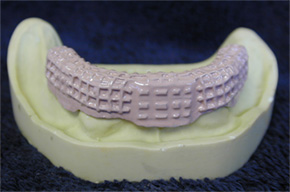
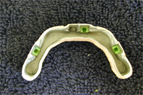
Step 6:Use Ropak light curing pink opaquer (Ropak liquid # 52000164; Ropak powder 52000165) to mask out the grey, metallic color of the overcasting. Install the 2.2mm SG green matrices.
VKS-SG/OC Bond-In Exchangeable Stud
Instructions for Use of VKS-SG/OC Bond-In Exchangeable Stud

1.A 1.7mm auxiliary modeling element (#450 000 73) is placed into a VKS paralleling mandrel and is waxed to the coping using a surveyor. The modeling element creates a 0.5mm larger receptacle to accommodate the cement used to bond in the threaded sleeve.

2.After wax has been applied around the auxiliary modeling element, it is carefully removed. Note: a vertical guide plane is created by applying wax directly onto the paralleling mandrel while waxing-in the modeling element.

3.Completed wax-up and ready to sprue for casting.

4.Lingual arm shoulder rest and groove are redefined and castings are finished as usual

5-Porcelain work is finished and metal areas are polished. Note: sandblast the hole lightly to remove any excess porcelain material.

6. 1.7mm titanium threaded sleeve, stud-head screw and screwdriver. *WARNING: Screwdriver is designed to break before screw head to avoid over torquing and breakage at the ball platform where the screwdriver engages.

7.Use high quality anaerobic cement and apply it evenly into the hole created by the auxiliary modeling element. NOTE: Make sure to insulate with separating medium any areas where bonding cement is not desired such as, the model, paralleling mandrel, etc.

8.Use the surveyor to insert the ball screw/threaded sleeve assembly into the receptacle coated with cement and allow it to set. Using the surveyor will ensure that the attachment is set absolutely parallel.

9.After the cement has set, release the mandrel from the attachment and inspect. At this time any excess cement can be picked off using a scalpel and fabrication of the RPD can begin.
VKS-SG / OC Exchangeable Stud Dimensions
| Product | Item # | Ø | Depth | Thread | Width | Height | |
|---|---|---|---|---|---|---|---|
|
|
Stud-head screw Stud-head screw |
450 000 47 450 000 56 |
2.2 mm Stud 1.7 mm Stud |
3.0 mm 3.8 mm |
M 2 x 0.25 M 1.6 x 0.2 |
- - |
3.5 mm 2.9 mm |
|
|
Thd sleeve oc 2.2 Thd sleeve oc 1.7 |
450 000 46 450 000 54 |
3.4 mm 3.4 mm |
- - |
- - |
- - |
1.7 mm 1.7 mm |
|
|
Threaded sleeve sg 2.2 Threaded sleeve sg 1.7 |
450 000 52 450 000 59 | - - - - |
1.7 mm 1.7 mm |
- - |
3.9 mm 3.0 mm |
5.1 mm 4.0 mm |


